
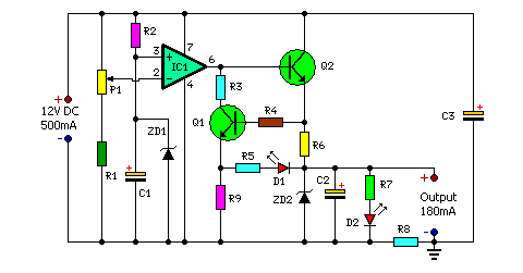
12 VOLT GEL CELL CHARGER
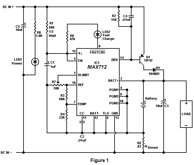
This circuit description pertains to a charger designed specifically for gel cell batteries, which are sensitive to overcharging and require specific charging protocols to ensure longevity and optimal performance. The charger employs an integrated circuit (IC) that manages the charging process through two distinct phases: fast charging and trickle charging.
In the fast charge phase, the charger delivers a constant current of 400 mA to the gel cell. This phase is initiated upon connecting a discharged gel cell. The IC monitors the battery voltage, and the fast charge continues until either the voltage stabilizes, indicating that the battery is nearing full charge, or a predetermined time limit of 4.5 hours is reached. This dual condition ensures that the battery is charged efficiently while also preventing potential damage from prolonged charging.
Once the fast charge phase concludes, the IC transitions to a trickle charge mode, where the charging current is reduced to approximately 50 mA. This lower charging rate is essential for maintaining the battery at a full charge without overcharging it. The trickle charge continues until the battery voltage reaches 13.8 volts, at which point the charging current is completely halted. This voltage threshold is critical, as it signifies that the battery is fully charged and ready for use.
Additionally, the circuit incorporates a feedback mechanism that allows the IC to detect any drop in battery voltage. Should the voltage fall below a certain level, the charger will automatically reinitiate either the fast or trickle charge mode, depending on the state of the battery. This feature ensures that the battery remains charged and reduces the risk of deep discharge, which can significantly shorten the battery's lifespan.
For practical implementation, it is recommended to attach a small heat sink to the transistor Q1, which is likely involved in regulating the charging current. This precaution is necessary to dissipate heat generated during operation, especially during the fast charge phase. Furthermore, the circuit requires a DC voltage supply of at least 15.3 volts, which must be maintained even under load conditions to ensure proper charging functionality. Utilizing a suitable DC wall transformer that meets these voltage requirements is crucial for the reliable operation of the charger.When a discharged gel cell is connected, the charger goes into a fast charge mode at a fixed rate of 400 ma. After the chip detects the voltage leveling off or when 4 1/2 hours has elapsed. (which ever happens first.) the fast charge will stop. After the fast charge has ended, the IC goes into a trickle charge rate of about 50 ma. This trickle charge continues until 13.8 volts is reached which will stop all charging current since the cell is now fully charged.
If the cell voltage should drop for any reason, either a fast charge or trickle charge (IC will detect what is needed) will start again. When constructing this circuit, be sure to attach a small heat sink to Q1. Apply a DC (partially filtered) voltage of at least 15.3 volts. The voltage must never go below this level even under load conditions. Many of the DC wall transformers available wi 🔗 External reference
Related Circuits
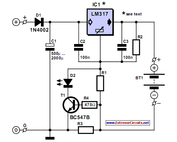
A simple NiCd charger can be constructed using readily available components and an economical LM317 or 78xx voltage regulator. The design incorporates a current limiter made up of resistor R3. The proposed NiCd charger circuit utilizes an LM317 or a...
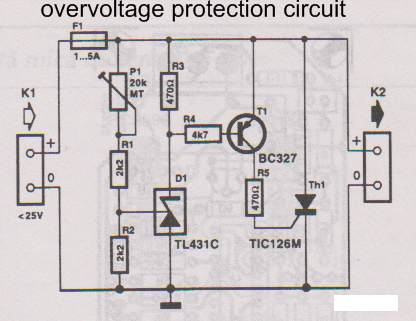
This overvoltage protection or crowbar protection circuit is used where protection against high voltage surges is necessary. The circuit consists of several components. This overvoltage protection circuit, commonly referred to as a crowbar circuit, serves as a critical safety mechanism...
This device includes a ringing generator and a tone oscillator. The tone oscillator is configured to operate at either 350 Hz or 440 Hz. The ringing generator is a sealed module providing 86 Vac at 20 Hz. Upon application...
Charges and protects your mobile phone from voltage spikes and short circuits. Most mobile chargers do not have current or voltage regulation, nor do they provide short-circuit protection. The described circuit functions as a mobile phone charger designed to safeguard...

This is a circuit design for a digital voltmeter with an LED display. It is suitable for measuring the output voltage of a DC power supply. The circuit features a 3.5-digit LED display with a negative voltage indicator and...
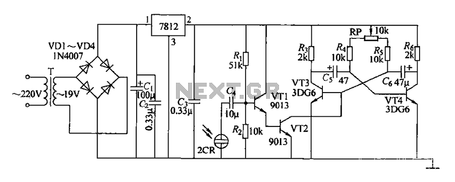
220V AC voltage is transformed by transformer T to 19V. After passing through a full-wave bridge rectifier and filter capacitor C, the voltage is regulated to DC using a 7812 voltage regulator. When the battery indicator light is illuminated,...
Warning: include(partials/cookie-banner.php): Failed to open stream: Permission denied in /var/www/html/nextgr/view-circuit.php on line 713
Warning: include(): Failed opening 'partials/cookie-banner.php' for inclusion (include_path='.:/usr/share/php') in /var/www/html/nextgr/view-circuit.php on line 713