
120 and 240Vac LED Indicator
The described circuit functions as a voltage level indicator for AC power lines, specifically designed to signal transitions between 120V and 240V. This circuit can be particularly beneficial in applications where monitoring supply voltage is critical for safety and operational purposes.
The primary components of the circuit include two diodes (D3 and D6), which serve as visual indicators, and a combination of transistors (Q1 and Q2) that provide latching functionality. The operational principle is based on the detection of voltage levels using the forward bias characteristics of the diodes.
When the input voltage approaches 120V AC, diode D3 becomes forward-biased, causing it to illuminate. This visual indication remains active even as the voltage increases to 240V, ensuring that users are aware of the voltage level at all times. The circuit is designed to retain this state due to the latching mechanism provided by the transistors.
Conversely, diode D6 is configured to illuminate only when the voltage reaches approximately 240V AC. At this point, the latching action of the transistors ensures that D6 remains lit, providing a clear indication of the higher voltage level. The transistors are likely configured in a feedback loop that maintains their conductive state once activated, allowing for a reliable indication of the voltage status.
This circuit can be integrated into various applications, including power distribution systems, industrial equipment, and home electrical systems, where voltage monitoring is essential. By providing visual signals at critical voltage thresholds, it enhances safety and operational awareness, allowing for timely interventions if necessary.
Overall, the circuit's design effectively combines simple components to achieve a reliable and functional voltage indication system, suitable for a range of electrical applications.This circuit, designed on request, has proven to be useful to indicate when the voltage in a power supply line is changing from 120V to 240Vac. It can be used in different circumstances and circuits, mainly when an increase in ac or dc supply voltage needs to be detected.
D3 illuminates when the line voltage is approaching 120V and will remain in the on state also at 240V supply. On the other hand, D6 will illuminate only when the line voltage is about 240V and will stay on because the latching action of Q1, Q2 and related
🔗 External reference
Related Circuits
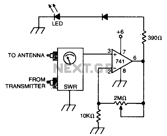
An operational amplifier (op amp) receives a direct current (DC) input from a standing wave ratio (SWR) meter, which can be adjusted to preset the SWR reading at which the light-emitting diode (LED) activates. The circuit involves an operational amplifier...
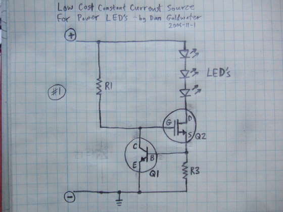
Here is a simple and cost-effective Power LED driver circuit. This power LED driver circuit is designed to efficiently drive high-power LEDs with a stable output. The circuit typically consists of a few key components: a power supply, a current...
The 555 circuit below is a flashing bicycle light powered with three C or D cells (4.5 volts). The two flashlight lamps will alternately flash at an approximate 1.5 second cycle rate. Using a 4.7K resistor for R1 and...
This document presents the circuit diagram of an IC-controlled emergency light with a charger, which functions as a 12V to 220V AC inverter circuit. The primary features of this circuit include automatic activation of the light during mains failure...

This is a flasher circuit that directly derives power from AC to produce brilliant flashes at a rate of one flash per second. It utilizes a DIAC as the main element. The flasher circuit operates by converting alternating current (AC)...

On most FM tuners, the stereo indicator activates upon detection of the 19-kHz pilot tone. However, this does not guarantee that the program is actually stereophonic, as the pilot tone is frequently transmitted alongside mono programs. A similar scenario...