
12KV High Voltage Generator
The 12kV High Voltage Generator is designed for applications requiring high voltage output while maintaining low current levels. The circuit architecture comprises two silicon-controlled rectifiers (SCRs) that operate in tandem to manage the discharge cycle of a capacitor. The capacitor, rated at 0.047 µF and 400V, serves as the energy storage element that is rapidly discharged through a xenon lamp, which acts as a trigger mechanism. This discharge occurs at a frequency of 120 Hz, resulting in the generation of high voltage pulses.
The output of the SCRs is connected to a pair of 6kV damper diodes that rectify the high voltage pulses, converting them from alternating current to direct current. This rectification process is crucial for charging the voltage doubler circuit, which is responsible for increasing the voltage to the desired level. The voltage doubler circuit consists of two high voltage disc capacitors that can each withstand voltages up to 12kV.
It is important to note that while the generator can produce high voltage, the current output remains relatively low, which could lead to inaccuracies in applications requiring precise measurements. Additionally, the high voltage output poses significant safety risks, as a 12kV spark can arc approximately 0.75 inches, emphasizing the need for careful design practices. Adequate spacing between components and proper insulation must be implemented to prevent unintended discharges and ensure safe operation. The overall design of the circuit must prioritize both performance and safety, making it suitable for specialized applications in high voltage environments.The 12KV High Voltage Generator beneath uses an abnormal adjustment to accomplish about 12, 000 volts with about 5uA of current. Two SCRs anatomy two beating architect circuits. The two SCRs acquittal a 0. 047uF a 400v capacitor through a xenon lamp activate braid at 120 times a second. The aerial voltage pulses produced at the accessory of the acti vate braid are rectified application two 6KV damper diodes. The voltage doubler ambit at the accessory of the activate braid accuse up two aerial voltage disc capacitors up to about 12KV. Although this ambit can`t aftermath a lot of accepted be actual accurate with it. A 12KV atom can jump about 0. 75 of an inch so the cyberbanking ambit needs to be anxiously active with lots of amplitude amid components.
🔗 External reference
Related Circuits
These are plans for an EMP generator. It utilizes flash circuits from disposable cameras to power the coil. An instructable will be created soon. The EMP generator design described involves utilizing the high-voltage flash circuits found in disposable cameras. These...
555 Variable Frequency Square Wave Generator. This simple 555 Variable Frequency Square Wave Generator produces a variable frequency output. The 555 Variable Frequency Square Wave Generator is a versatile circuit that utilizes the 555 timer IC to generate square wave...
This circuit will activate the LED when the monitored voltage drops below the values determined by the Zener diodes D1 and D2. The circuit utilizes Zener diodes to establish reference voltage levels, which are critical for monitoring voltage thresholds. The...
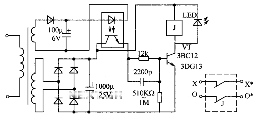
The circuit protection mechanism utilizes optocouplers for on-off control. Under normal voltage conditions, the output from the optocouplers is minimal, and the VT transistor operates in reverse bias. However, if the circuit voltage increases due to reasons such as...
This circuit generates sine, square, and triangle waves ranging from 0.1 Hz to 1 MHz. It includes a counter that measures the frequency of the function generator or an external signal with a peak-to-peak voltage of a few volts,...
The input voltage for the high-voltage DC-DC converter is 12V AC at 800mA, which is then converted to DC using a 1A bridge rectifier diode. The output voltage of the converter can be adjusted within the range of 0-1000V...