
12V Speed Controller/Dimmer
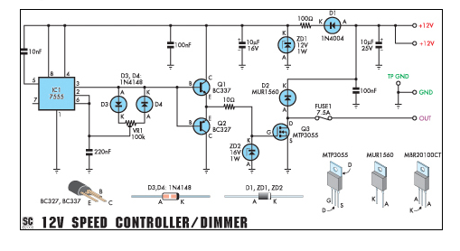
The circuit utilizes a pulse-width modulation (PWM) technique to regulate the speed of the motor or the brightness of the light. It typically consists of a microcontroller or a dedicated PWM controller IC, a power transistor or MOSFET to handle the load, and passive components such as resistors and capacitors for filtering and stability.
For the motor speed control application, the circuit adjusts the duty cycle of the PWM signal, which effectively controls the average voltage supplied to the motor. This allows for smooth acceleration and deceleration, enhancing the motor's performance while minimizing heat generation. The circuit may include additional features such as overcurrent protection to safeguard the motor from excessive current draw.
In the dimmer application, the PWM signal modulates the power delivered to the light source, allowing for a range of brightness levels. This method is more efficient than traditional resistive dimmers, as it reduces wasted energy and heat, making it suitable for long-term use.
The circuit should be designed with adequate heat sinking for the power transistor or MOSFET, especially when operating at higher currents. Proper selection of components, including the PWM frequency, will ensure optimal performance for both motor control and dimming applications.This handy circuit can be used as a speed controller for a 12V motor rated up to 5A (continuous) or as a dimmer for a 12V halogen or standard incandescent.. 🔗 External reference
Related Circuits
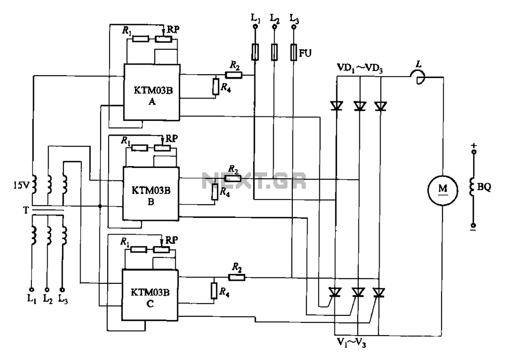
Adjusting the phase potentiometer RP can change the conduction angle of each corresponding thyristor (V1-V). This adjustment alters the voltage applied across the load. The circuit utilizes a phase control technique to manage the power delivered to a load by...
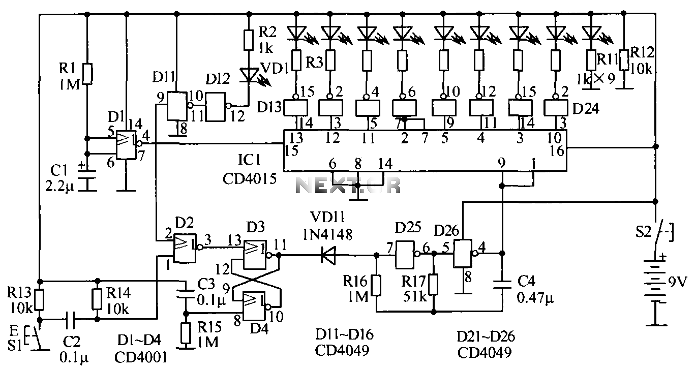
The circuit for testing human reaction speed is illustrated in the figure. It includes NAND gates D25 and D26, along with other components that generate a multivibrator output clock pulse with a period of approximately 50 milliseconds. The circuit...
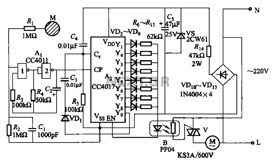
The circuit depicted in Figure 3-7 utilizes a touch sensor chip in conjunction with a conductive sheet. It is designed to achieve eight different speed settings. The CC4011 timing pulse oscillator is comprised of an integrated circuit. The configuration...
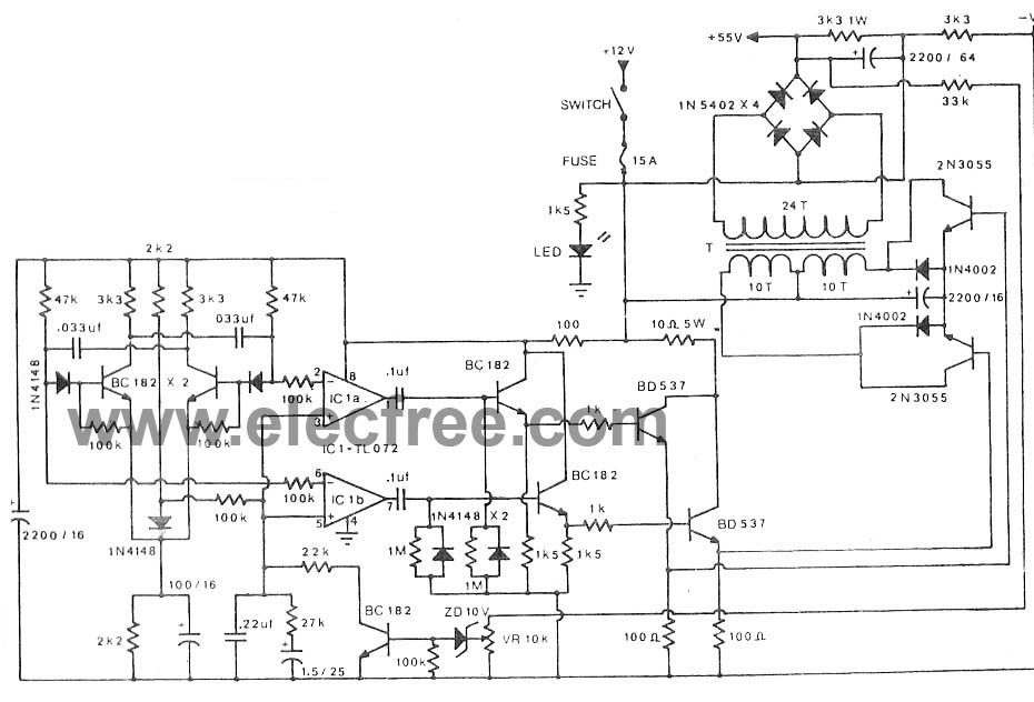
A main component along with a 2N3055 transistor and an IC TL072 is utilized in the pulse oscillator generator. The output voltage reaches +50V and -50V, providing a current of 2A to 3A. The circuit employs a 2N3055 transistor, which...

Symmetric 12V to 5V converter power supply. Refer to the designated page for an explanation regarding the associated circuit diagram. The symmetric 12V to 5V converter power supply is designed to efficiently step down a 12V input voltage to a...
This circuit is capable of automatically charging 6V and 12V batteries quickly and accurately. A key factor in the successful operation of the circuit is the use of a high-quality transformer (T1) that features excellent insulation and short-circuit resistance. The...
Warning: include(partials/cookie-banner.php): Failed to open stream: Permission denied in /var/www/html/nextgr/view-circuit.php on line 713
Warning: include(): Failed opening 'partials/cookie-banner.php' for inclusion (include_path='.:/usr/share/php') in /var/www/html/nextgr/view-circuit.php on line 713