
12vdc to 37v dc converter
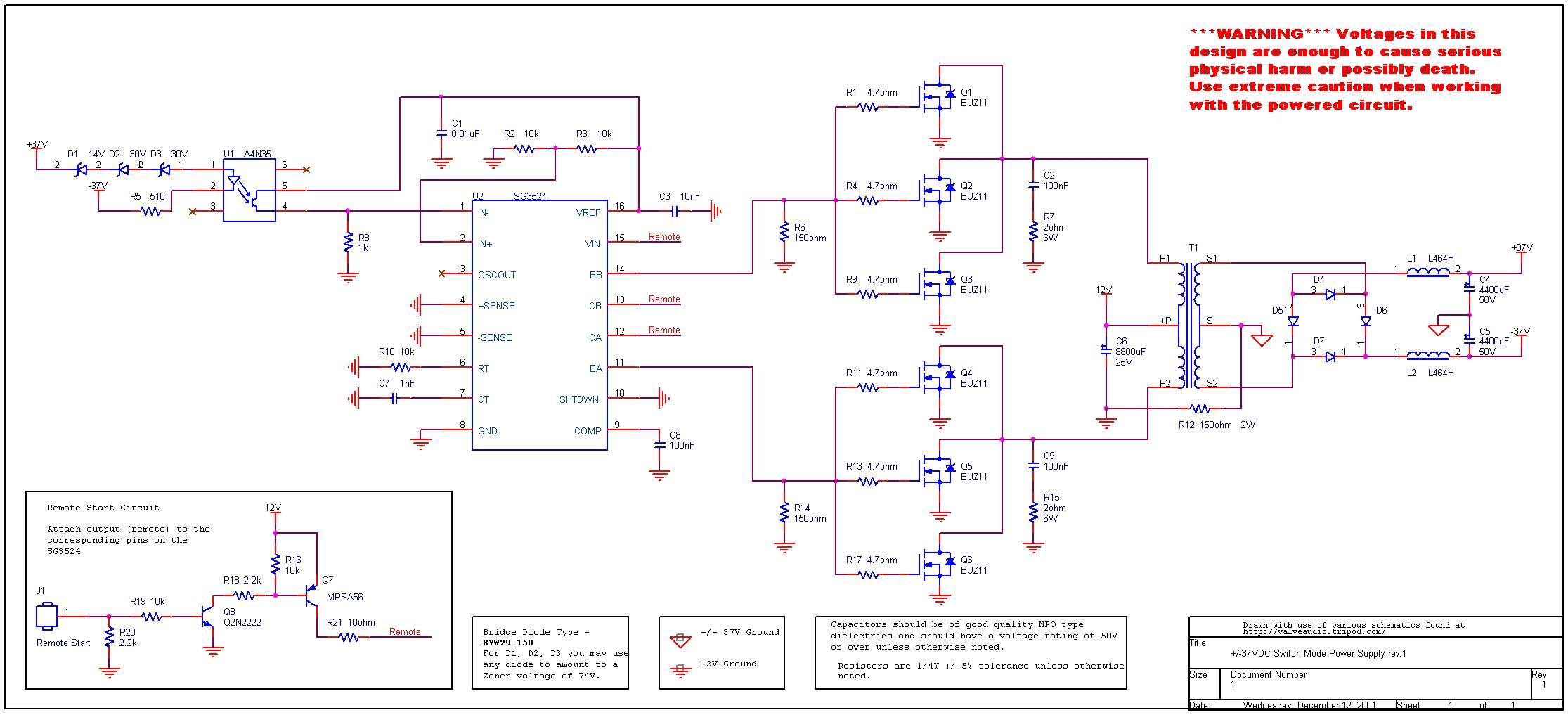
The circuit described is a DC to DC converter designed to convert an input voltage of 12V DC to an output voltage ranging from 0V to 37V DC. This circuit utilizes the SG3524 integrated circuit, which is a versatile PWM (Pulse Width Modulation) controller. The SG3524 is capable of driving external power transistors to achieve the desired voltage levels.
The circuit operates by first generating a PWM signal that controls the duty cycle, which in turn regulates the output voltage. The input voltage is fed into the SG3524, where it is compared against a reference voltage. The output of this comparison adjusts the PWM signal, which is then used to drive a switching transistor or MOSFET. This transistor rapidly switches on and off, allowing energy to be stored in an inductor or transformer, which is then released to produce the desired output voltage.
To achieve the output range from -37V to +37V, the circuit may include additional components such as a center-tapped transformer or a dual power supply configuration. The feedback mechanism is crucial for maintaining voltage stability and ensuring that the output voltage remains within the specified limits under varying load conditions.
Key components in the circuit include:
- SG3524 IC: The main control unit responsible for PWM generation.
- Inductor: Used for energy storage during the switching cycle.
- Diodes: Used for rectification to convert the AC output from the transformer back to DC.
- Capacitors: Employed for smoothing the output voltage and filtering noise.
- Resistors: Used for setting the reference voltage and feedback loop.
This converter is suitable for applications requiring a stable DC voltage in environments where the input voltage may vary or where a higher output voltage is needed for specific electronic devices or systems. Proper design considerations must be taken into account, including component ratings, thermal management, and layout to ensure reliable operation.12VDC to 37V DC converter by SG3524 Hello there!! How are you doing? When my friend of I wants DC to DC converter circuit +37V GND -37V sizes use an.. 🔗 External reference
Related Circuits
The circuit diagram illustrates two LT1398 operational amplifiers from Linear Technology utilized to generate buffered color-difference signals from RGB (red-green-blue) inputs. In this setup, the R input is received through a 75-ohm coaxial cable and directed to the non-inverting...
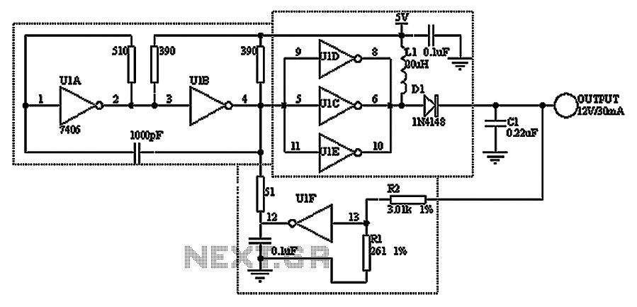
A TTL hex inverter circuit can function as a DC/DC converter, converting 5V to 12V. This circuit encompasses all necessary functionalities for DC/DC conversion. It relies on a TTL switching threshold voltage regulator. The components U1A and U1B form...
A 6V to 12V DC converter circuit is designed to convert a lower voltage of approximately 6 volts to a higher voltage of 12 volts, albeit with a reduced current rating. This inverter circuit can deliver up to 800mA...
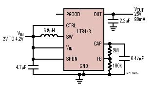
The LT3473 and LT3473A are micropower step-up DC/DC converters that integrate a Schottky diode and output disconnect circuitry within low-profile DFN packages. Their compact size, high integration level, and utilization of small surface-mount technology (SMT) components result in a...
This project is a VGA-to-Scope converter that utilizes composite video signals instead of VGA signals to display on an oscilloscope. The design has been simplified by removing op-amp buffers and inverters. A simple 1 Megohm potentiometer is used to...
This circuit can be used to receive AM stations in an FM radio. It is a regenerative circuit that samples AM signals of all frequencies and retransmits them in the FM band or in the TV band. The described circuit...
Warning: include(partials/cookie-banner.php): Failed to open stream: Permission denied in /var/www/html/nextgr/view-circuit.php on line 713
Warning: include(): Failed opening 'partials/cookie-banner.php' for inclusion (include_path='.:/usr/share/php') in /var/www/html/nextgr/view-circuit.php on line 713