
13.8V 40A Switching Power Supply By LM3524 and LM324 PCB

The half bridge forward converter topology is characterized by its efficiency and simplicity, making it a popular choice for power supply applications. The design consists of a transformer that provides isolation and voltage step-up or step-down capabilities, paired with a bridge configuration of two power transistors that alternately switch the current through the primary winding of the transformer. This arrangement allows for effective control of the output voltage and current by varying the duty cycle of the switching signals.
In this design, the choice of using bipolar transistors is significant. Although they exhibit slower switching speeds compared to MOSFETs, their lower conduction losses contribute to a more stable operation at lower frequencies. The proportional driving technique employed ensures that the transistors operate within optimal parameters, adapting to varying load conditions while minimizing switching losses and heat generation.
The PWM control method is implemented using the 3524 IC, which is designed for power supply applications. This IC simplifies the generation of the required control signals, providing a stable and reliable means of regulating the output voltage. By adjusting the duty cycle of the PWM signal, the effective output voltage can be finely tuned to meet the specific requirements of the application.
The choice of a switching frequency of 25 kHz is a deliberate design decision aimed at minimizing RF noise, which can be a significant issue in power supply designs. While higher frequencies can lead to smaller transformer sizes and improved efficiency, they also require more complex filtering solutions to manage the resultant electromagnetic interference (EMI). The frequency doubling effect of the rectifiers, leading to an effective output frequency of 50 kHz, is an important consideration in the design of the output filter, which must be capable of handling this frequency while maintaining the desired output quality.
Overall, this half bridge forward converter design provides a robust solution for power supply applications, balancing efficiency, simplicity, and performance while addressing the challenges associated with RF noise and component selection.This article was originally published (in a slightly modified form) in the QST magazine, December 1998 and January 1999, and in the Radio Amateur`s Handbook, 1999. Visit the American Radio Relay League for information on these publications, and a world of ham radio related things!
There are several different topologies for switchers in common use, and the first decision a designer must take is which of them to consider. Among the factors affecting the decision are the power level, the number of outputs needed, the range of input voltage to be accepted, the desired tradeoff between complexity, quality and cost, and many more. For this power supply I decided to use the half bridge forward converter design. This topology connects the power transformer to a bridge formed by two power transistors and two capacitors.
It is reasonably simple, puts relatively low stress on the power transistors, and makes efficient use of the transformer`s magnetic capabilities. The second basic decision is which switching frequency to use. The present trend is to use ever higher frequencies. But by doing so it becomes more difficult to filter out the RF noise inevitably generated by the switching.
So I decided to stay at a low switching frequency of only 25 kHz for the full cycle, which due to the frequency doubling effect of the rectifiers results in 50 kHz on the output filter. For the main switching elements, bipolar transistors or MOSFETs can be used. Bipolars have lower conduction losses, while MOSFETs switch faster. As in this design I wanted to keep the RF noise at an absolute minimum, very fast switching was not desired, so I used bipolar transistors.
But these tend to become too slow if the driving is heavier than necessary. So, if the transistors have to switch at varying current levels, the drive to them must also be varied. This is called proportional driving, and is used in this project. The half bridge converter is best controlled by pulse width modulation. There are several ICs available for this exact purpose. I chose the 3524, which is very simple to use and easy to find. Any 3524 will do the job. It can be an LM3524, SG3524, etc. 🔗 External reference
Related Circuits
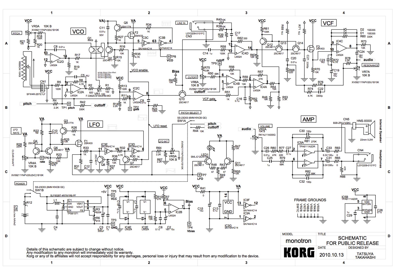
A voltage-controlled oscillator (VCO) using the LM324 operational amplifier is being developed, inspired by the Korg Monotron schematic. The goal is to create a simple circuit that produces audible waveforms, specifically square and triangle waves, when connected to a...
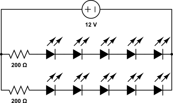
A 12V power supply is available, and there is a need to power LEDs with a forward voltage of 2V. It is questioned whether only six LEDs can be powered or if the cathode of one LED can be...
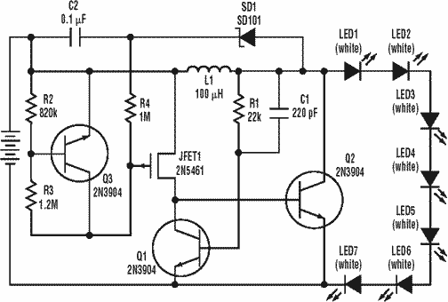
A low power, long-life LED flashlight circuit. Electronic Design proposed a simple circuit to resolve this in a recent article. The front end of their circuit draws less than a milliamp of extra current. The described LED flashlight circuit is...
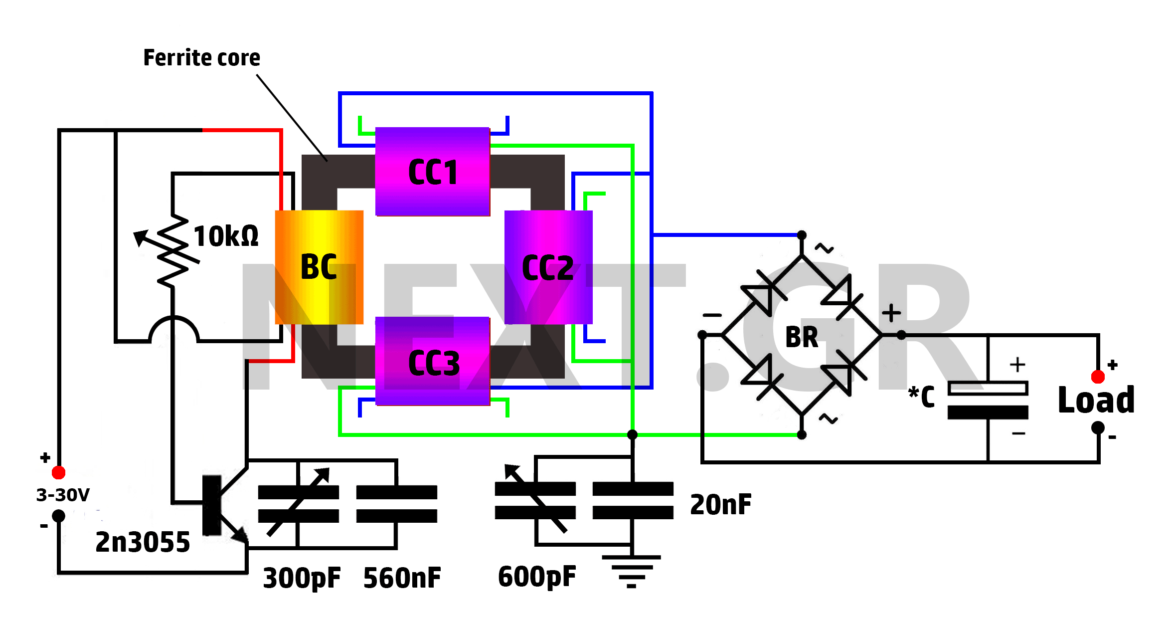
This is a Tesla/joule thief hybrid circuit that its inventor claims can produce 90 times the input power. The circuit can be self-looped and can provide 1050W of power, with only 11.6W looping back to supply the joule thief....
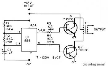
The first section of the 555 timer is configured as an astable oscillator, with resistors R2 and capacitor C1 determining the frequency. The output is available at pin 5. The second section is set up as a phase inverter,...
The electronic switch functions as a multifunctional preamplifier. It features a five-way touch electronic switch, a high-speed DC servo RIAA ultralow distortion amplifier, and can control volume, tone, and power amplifier electrical path phase. The TC9152, shown in Figure...