
15 Watt Amplifier
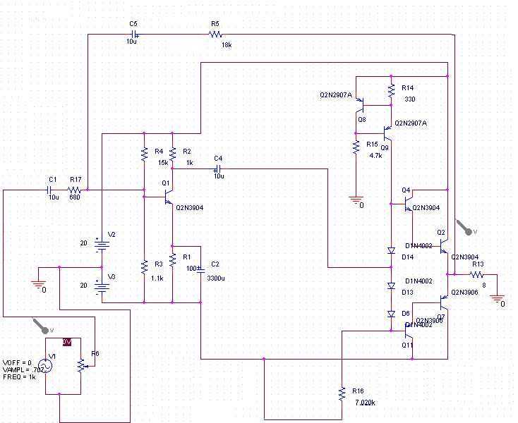
The circuit described is a 15-watt audio amplifier designed to interface with standard audio sources such as walkmans or CD players, accepting a nominal input signal of 500 mV RMS. The amplifier operates from a dual 20 Volt power supply, which allows it to efficiently deliver 15 watts of power into an 8-ohm load, making it suitable for driving small speakers or headphones.
The input stage of the amplifier utilizes a common emitter configuration with transistor Q1, which amplifies the incoming audio signal. The biasing of Q1 is critical for ensuring linear operation and minimizing distortion. This biasing is achieved through a bias chain that includes transistors Q8 and Q9, along with diodes D6, D13, and D14. The role of Q8 and Q9 is to provide a constant current through the bias network, which stabilizes the operating point of Q1 and enhances the overall linearity of the amplifier.
The output stage is constructed using a discrete Darlington pair configuration, which consists of two transistors that work together to provide high current gain. This design choice allows the amplifier to drive the load effectively while maintaining good thermal stability and efficiency. The use of discrete components in this amplifier design offers advantages such as improved sound quality, customization potential, and ease of repair compared to integrated circuit solutions.
Overall, this amplifier circuit exemplifies a well-thought-out design for audio applications, balancing power output, distortion control, and component selection to achieve a robust and reliable performance.You can use this circuit with any walkman or CD player since it is designed to take a standard 500mv RMS signal. A 15 watt amplifier made using discrete components. Sergio designed this circuit for his Electronics Level II course. This amplifier uses a dual 20 Volt power supply and delivers 15 watts RMS into an 8 ohm load. Q1 operates in common emitter, the input signal being passed to the bias chain consisting of Q8, Q9, D6, D13 and D14. Q8 and Q9 provide a constant current through the bias chain to minimize distortion, the output stage formed by a discrete darlington pair
🔗 External reference
Related Circuits
The circuit is based around LM4702 manufactured by NATIONAL semiconductors MJ11029-MJ11028 by ON semiconductors. It is a high fidelity audio power amplifier designed for demanding consumer and pro-audio applications. You can also use this circuit with AV receivers, audiophile...
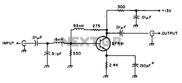
The amplifier delivers a gain of 10 dB across a frequency range of 10-600 MHz and features a 1-to-1 impedance match at 50 ohms. The BFR91 transistor exhibits a noise figure of 1 dB at 500 MHz. The circuit...
The CL type circuit is not a power amplifier output capacitance, feedback capacitance, or compensation capacitor amplifier circuit; it operates solely through a transistor (or FET) and a resistor. This circuit can generate feedback, and phase shift elements are...
A common telecoil follows the MM formula (magnetic-acting) and has an impedance of approximately 600 ohms to effectively receive signals. It is necessary to reduce the impedance in the high-frequency segment, which is achieved by placing a 150pF capacitor...
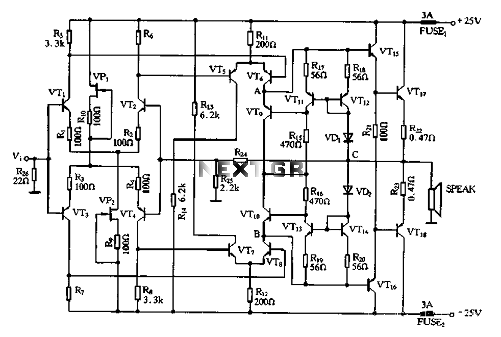
This circuit utilizes a MOSFET amplifier as the primary component for boosting audio signals. It is designed to drive a speaker with an impedance of 8 Ohms and a power output exceeding 200W. Additionally, a suitable power supply circuit...
The preamp circuit is completely conventional, and by necessity is AC coupled throughout. The artificial earth is derived by two resistors (R1 and R2), which will set the "earth" at exactly 1/2 the supply voltage. This is nominally 13.8V...
Warning: include(partials/cookie-banner.php): Failed to open stream: Permission denied in /var/www/html/nextgr/view-circuit.php on line 713
Warning: include(): Failed opening 'partials/cookie-banner.php' for inclusion (include_path='.:/usr/share/php') in /var/www/html/nextgr/view-circuit.php on line 713