
1500 Watt RF Amplifier Circuit
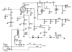
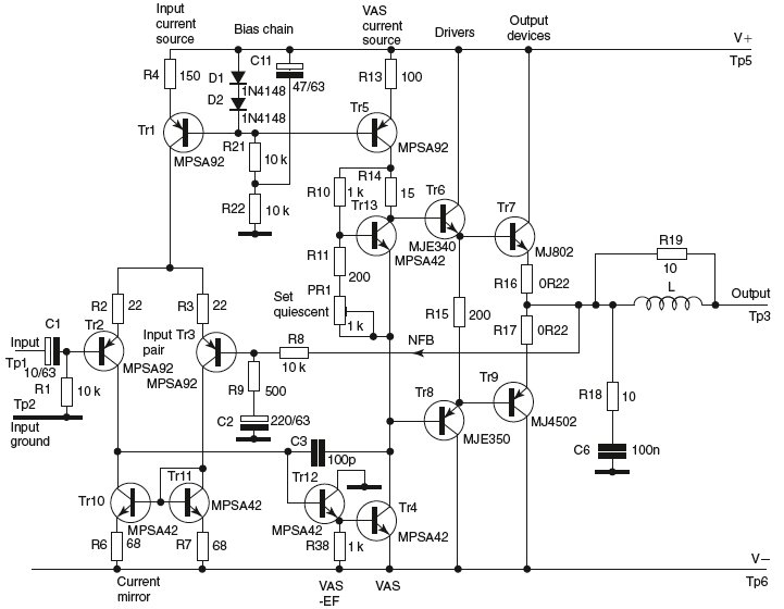
The 1500 Watt RF Amplifier circuit is designed to amplify radio frequency signals, making it suitable for various applications in the field of telecommunications and microwave technology. This amplifier is capable of driving a transmitter antenna, ensuring that the RF signal is transmitted with sufficient power to reach the desired range.
The circuit typically consists of high-power transistors or RF power MOSFETs that are configured in a push-pull arrangement to enhance efficiency and linearity. The input stage of the amplifier may include impedance matching networks to optimize the power transfer from the source to the amplifier. This is crucial for minimizing signal reflections and maximizing output power.
The design may also incorporate a heat sink or cooling system, as high power levels can generate significant heat that must be dissipated to prevent damage to the components. Additionally, the amplifier circuit may include protection features such as over-temperature shutdown, over-current protection, and RF output monitoring to ensure reliable operation.
For microwave heating applications, the amplifier can be configured to operate at specific frequencies, allowing it to efficiently deliver energy to materials for heating purposes. This versatility makes the 1500 Watt RF Amplifier a valuable component in various industrial, scientific, and telecommunications applications.
Overall, the 1500 Watt RF Amplifier circuit represents a robust solution for high-power RF amplification, offering flexibility for a range of uses from driving antennas to facilitating microwave heating processes.1500 Watt RF Amplifier circuit can be used to drive your transmitter antenna, it can also include driving to the source of the RF high power, microwave heating, and more. 🔗 External reference
Related Circuits

A GdS cell serves as one leg of a bridge circuit. Potentiometer R6 in another leg establishes the trip point. Potentiometer R5 allows for hysteresis adjustment to prevent chattering or hunting of the relay. The light level must increase...
The amplifier drives a pair of speakers using two LM3876 amplifier chip circuits (50 watts per channel) or a pair of headphones with Meier Crossfeed through a clarifier and a dual OPA2134 Opamp. It features four selectable band inputs...
High Quality unit with LM833 or NE5532 Low noise Dual Op-amp. No need for a preamplifier. Can be directly connected to CD players, tuners and tape recorders. Tested with several headphone models of different impedance: 32, 100, 245, 300,...
This circuit is very basic to build and puts out great power for your car or home. Keep all leads as short as possible. This circuit is designed to deliver substantial power output suitable for automotive or residential applications. The...
This circuit is an ultra-sensitive infrared (IR) receiver designed to control various AC devices via an IR transmitter. It utilizes a phototransistor... The ultra-sensitive IR receiver circuit is engineered to detect infrared signals emitted from an IR transmitter, enabling the...
This document discusses the advantages and disadvantages of various power supply technologies, along with the design considerations necessary for selecting and evaluating a mains transformer. It covers the pros and cons of external supplies, inrush current control, RF emissions...
Warning: include(partials/cookie-banner.php): Failed to open stream: Permission denied in /var/www/html/nextgr/view-circuit.php on line 713
Warning: include(): Failed opening 'partials/cookie-banner.php' for inclusion (include_path='.:/usr/share/php') in /var/www/html/nextgr/view-circuit.php on line 713