
15db uhf tv antenna booster circuit

This UHF TV antenna circuit operates by amplifying weak signals received by the antenna, enhancing the overall signal quality for better reception. The circuit's design incorporates a band-pass filter in the first stage, which selectively allows frequencies within a certain range while attenuating out-of-band signals. This helps to improve the signal-to-noise ratio by filtering out unwanted frequencies that could degrade performance.
The components C1, CV1, L1, L4, C7, and C3 are strategically chosen to define the filter's characteristics, such as its center frequency and bandwidth. The air-core coils (L1 to L4) are essential for maintaining a high Q-factor, which is a measure of the filter's selectivity and efficiency. A higher Q-factor indicates that the circuit can more effectively resonate at the desired frequency while rejecting others.
The second stage of the circuit utilizes a base-common voltage amplifier configuration. This configuration is known for its low input impedance, which is beneficial for matching with the output of the band-pass filter. Proper impedance matching is crucial for maximizing power transfer and minimizing reflections that can lead to signal loss.
After the circuit is assembled, it is important to place it inside a metallic enclosure. This not only protects the circuit from physical damage but also shields it from electromagnetic interference (EMI) that could affect performance. By connecting the circuit's ground to the metallic box, any noise picked up by the circuit can be effectively grounded, further enhancing the signal integrity.
Overall, this UHF TV antenna circuit design emphasizes simplicity and efficiency while ensuring optimal performance through careful component selection and layout.This is a circuit for antenna UHF TV that can be give 15dB preamp. This circuit is built by transistor and low components. This is the figure of the circuit. The circuit above is formed based on BF180 UHF Transistor. The first stage is a band pass filter constructed by the C1, CV1, L1, L4, C7 and C3, the second stage is a base-common voltage ampli fier with low input impedance to match. Build the L1 ~ L4 as air core coil to obtain high Q-Factor. After assembling, pack it into a proper metallic box and connect the ground of the circuit to the box to reduce noise effect. 🔗 External reference
Related Circuits
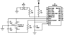
The following file contains detailed information about the design of a basic clock oscillator circuit diagram. Included in this file is information about selecting the components. The clock oscillator circuit is a fundamental component in various electronic systems, providing a...
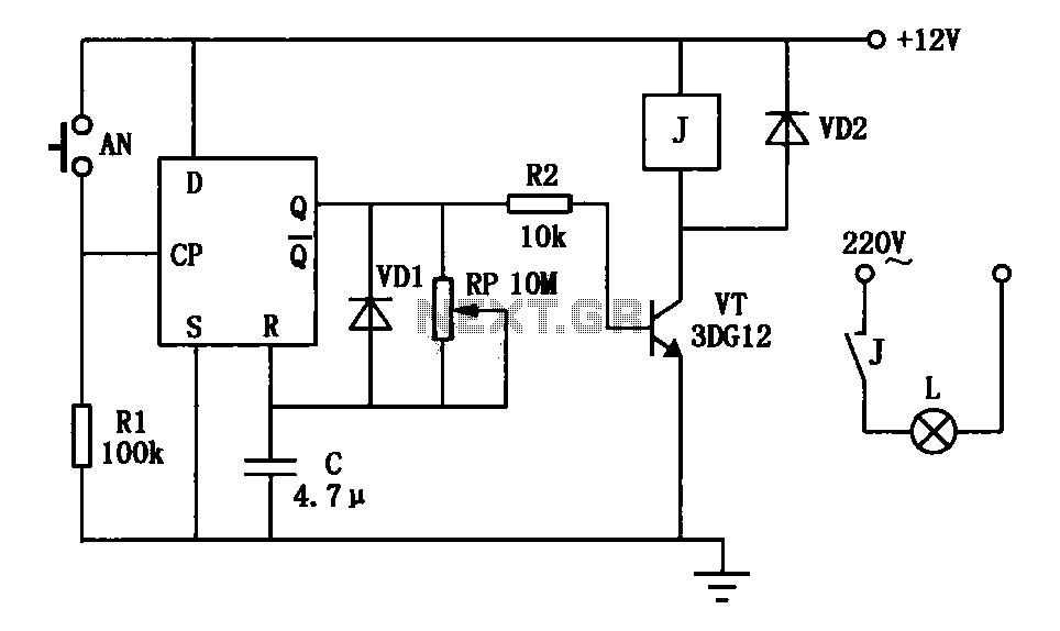
An exposure timer circuit is illustrated using D flip-flops, allowing for timing adjustments between 1 to 30 seconds. The D flip-flop circuit is connected to a one-shot timer. When exposure is required, pressing button AN generates a pulse that...
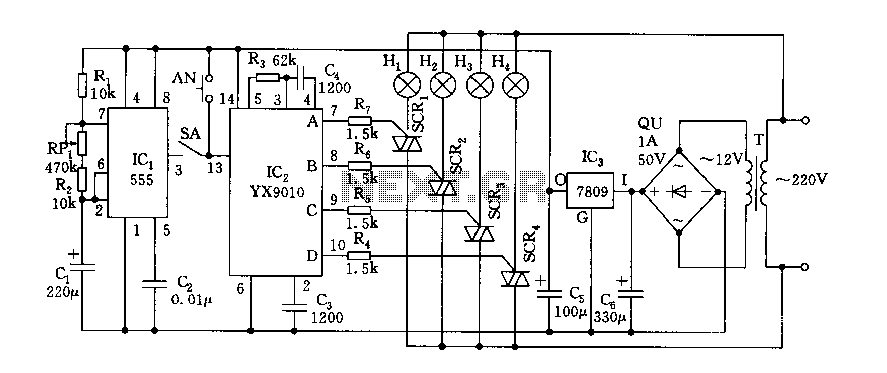
Fantasy lights offer wonderful changes suitable for storage, dance halls, or family holiday decorations. The control circuit is depicted here, which includes a multivibrator control circuit, a thyristor trigger circuit, and a step-down power supply circuit. The AC step-down...
This circuit is designed to indicate when a plant requires watering. An LED blinks at a low frequency when the soil in the flower pot is excessively dry, turning off as the moisture level rises. The sensitivity of the...
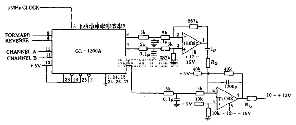
The error processing segment is converted into a pulse width modulated (PWM) signal output from 3 feet (MC signal). Additionally, the differential position error is calculated, which represents the small velocity, from 6 to 7 feet, selected as a...
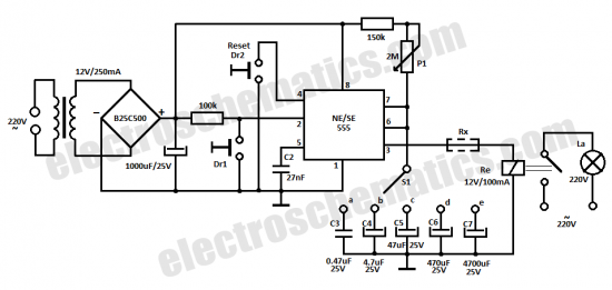
This time delay relay circuit is constructed using the NE/SE555 integrated circuit, manufactured by Intersil, which incorporates a precision timer. The circuit exhibits stability against temperature variations of 0.00. The NE/SE555 timer IC is a versatile device widely used in...