
16-300 MHz Testing Colpitts oscillator
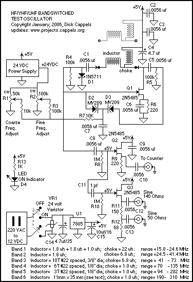
To make a 50 Ohm output, so the generator can drive a 50 Ohm cable, the output impedance of Q3 was measured while using a 220 Ohm source resistor. This was done by measuring the Peak-to-peak output voltage without a substantial load, at 20 MHz, then loading the source with an additional 470 Ohm resistor, and calculating the effective output resistance of the source follower based on the change in amplitude. This value was found to be about 139 Ohms. The output impedance is about 50 Ohms at 20 MHz, but this design approach does not separate out the resistive from the reactive part of the impedance, and it is expected that the impedance will change as a function of frequency.
Using a program that seeks numerical solutions to formulae, the values of resistors for R11 and R12 that simultaneously satisfy the requirement that the total resistance be equal to 220 Ohms and the resistance from the connection between R11 and R12 to ground, including the effects of the source follower, is equal to 50 Ohms were found. The values, R11 = 150 Ohms and R12 = 68 Ohms are the closest 5% resistor values.
The +24 volt power supply was made separately and is described separately on this site.
Construction
The oscillator subassembly was built, dead bug style, or "Ugly Bug" style on a piece of copper clad fiberglass board, that was in turn mounted to the bottom of a two section six pole rotary switch. The board is held to the switch with solder on the two solder tabs on the switch. The oscillator subassembly, mounted on the rotary switch, the +24 volt bias supply, and all of the other components are mounted in the box. The light colored phenolic board serves as both a mechanical adapter to hold the +24 volt supply to the plastic box and also holds the +5 volt regulator, the varistor, and the decoupling component. The aluminum cover is connected to the oscillator subassembly ground plane with a pair of gray wires. A short length of RG-174/U is used to connect the 50 Ohm signal to the RCA connector. Given the short length, it is suspected that this could have been twisted hook-up wire without a noticeable effect on performance. The counter output and the 150 Ohm, 640 millivolt (unterminated voltage) output are connected to their respective RCA connectors with twisted AWG 26 hook-up wire.
It may have been a little nicer to have put this into a fully shielded box, but the performance in a plastic box is satisfactory. The careful, compact construction over the ground plane provided by the copper clad board has worked well in the limited use of the test oscillator so far.
The hand-wound coils were wound on a drill bit. One trick to making nicely formed coils is to stretch the wire a little bit before starting the winding, and to keep tension on the wire through the winding process. This keeps the wire from unwinding. Once the coils are wound, they may require adjustment to achieve the desired frequency range. This adjustment consists of stretching or compressing the coil turns, which is often an art due to component variation.
Performance
The sine wave output is much cleaner than the counter output. The oscillator signal, when listened to on an FM radio receiver, is stable, exhibiting little short-term frequency drift. However, there is substantial drift from day to day, as indicated by the frequency meter. Evaluation of the performance is limited due to the lack of calibrated instrumentation that covers most of the oscillator's range.The circuit is a modified Colpitts oscillator, tuned with MV209 varactor diodes. The resonating inductor and the drain choke are selected by a rotary switch. 1N5711 Schottky diode, D, clamps the maximum positive voltage on the gate of oscillator FET, Q1 to just above ground to reduce the distortion in the wave form on the gate of Q1. Buffer Q2 provides about 1.8 volts peak-to-peak at 20 MHz to drive a frequency meter. Since the P-P voltage on the gate of Q1 is too large to be buffered by a 2N5485 without sever distortion -see the pictures further down this page), the signal is reduced by a capactitive voltage divider formed by 1 picofarad capacitor C11 and the input capacitance of Q3.
This results in about 650 millivolts on the gate of Q3, and about the same on the source. To make a 50 Ohm output, so the generator can drive a 50 Ohm cable, I measured the output impedance of Q3 while using a 220 Ohm source resistor. This was done by measuring the Peak-to-peak output voltage without a substantial load, at 20 MHz, then loading the source with an additional 470 Ohm resistor, and calculating the effective output resistance of the source follower based on the change in amplitude.
This value was found to be about 139 Ohms. This is much simpler and more direct than trying to calculate the output impedance as a function of data sheet values, since the key parameters such as IDon vary too widely to allow design without trimming. The output impedance is about 50 Ohms at 20 MHz, but this design approach does not separate out the resistive from the reactive part of the impedance, and I expect the impedance to change as a function of frequency.
Using a program that seeks numerical solutions to formulae, I found the values of resistors for R11 and R12 that simultaneously satisfy the requirement that the total resistance be equal to 220 Ohms and the resistance from the the connection between R11 and R12 to ground, including the effects of the source follower, is equal to 50 Ohms. The values, R11 = 150 Ohms and R12 = 68 Ohms are the closest 5% resistor values. The +24 volt power supply was made separately, and is described separately on this site. You can find it with this link: 5 Volt to 24 Volt DC to DC Converter. Construction The oscillator subassembly was built, dead bug style, or "Ugly Bug" style as a friend calls it, on a piece of copper clad fiberglass board, that was in turn mounted to the bottom of a two section six pole rotary switch.
The board is held to the switch with solder on the two solder tabs on the switch. The oscillator subassembly, mounted on the rotary switch, the +24 volt bias supply, and all of the other components mounted in the box. The light colored phenolic board serves as both a mechanical adapter to hold the +24 volt supply to the plastic box, and also holds the +5 volt regulator, the varistor, and the decoupling component.
The aluminum cover is connected to the oscillator subassembly ground plane with a pair of gray wires. A short length of RG-174/U is used to connect the 50 Ohm signal to the RCA connector. Given the short length, I suspect that this could have been twisted hook-up wire without a noticeable affect on performance.
The counter output and the 150 Ohm, 640 millivolt (unterminated voltage) output are connected to their respective RCA connectors with twisted AWG 26 hook-up wire. It may have been a little nicer to have put this into a fully shielded box, but I am quite happy with the performance in a plastic box.
I think the careful, compact construction over the groundplane provided by the copper clad board worked well in my limted use of the test oscillator so far. The hand-wound coils were wound on a drill bit (A trick mentioned by legendary Harry Lythall). One trick to making nicely formed coils is to stretch the wire a little bit before starting the winding, and to keep tension on the wire through the winding process.
This keeps the wire from unwinding. Once you have the coils wound, you will have to fiddle with them a little bit in order to get the frequency range you want. The fiddling consists of stretching the coil or compressing the turns. This part is art, and given the realities of component variation, this is a necessity. Performance Its clear that the sine wave output is much cleaner than the counter output. Listening to the signal on an FM radio receiver, the oscillator sounds quite and "feels" stable, that is to say there is little short term frequency drift.
There is substantial drift from day-to-day as indicated by the frequency meter. At the moment, that's about as far as I have been able to get in terms of evaluating the performance, since I don't curretnly posess calibrated instrumentation that covers most of the oscillator's range. 🔗 External reference
Related Circuits
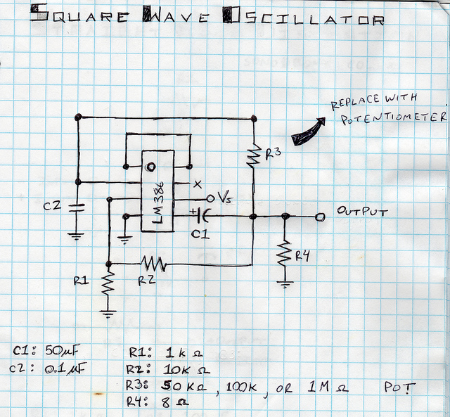
This is a square wave oscillator (digital, similar to 8-bit music). It is based on the LM386 amplifier integrated circuit, which is also the foundation for the mini guitar amplifier. The design includes a simple power switch connected to...
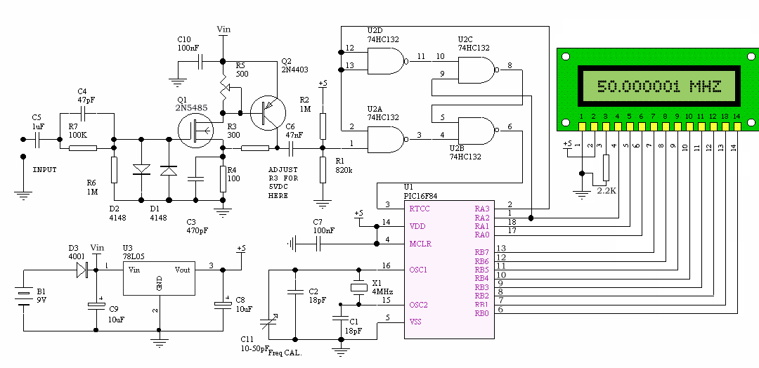
This project is a compact frequency counter capable of measuring frequencies from 1 Hz to 50 MHz, modified from the original design by Weeder Technologies. A new PCB has been designed to accommodate a 16x1 LCD, and the source...
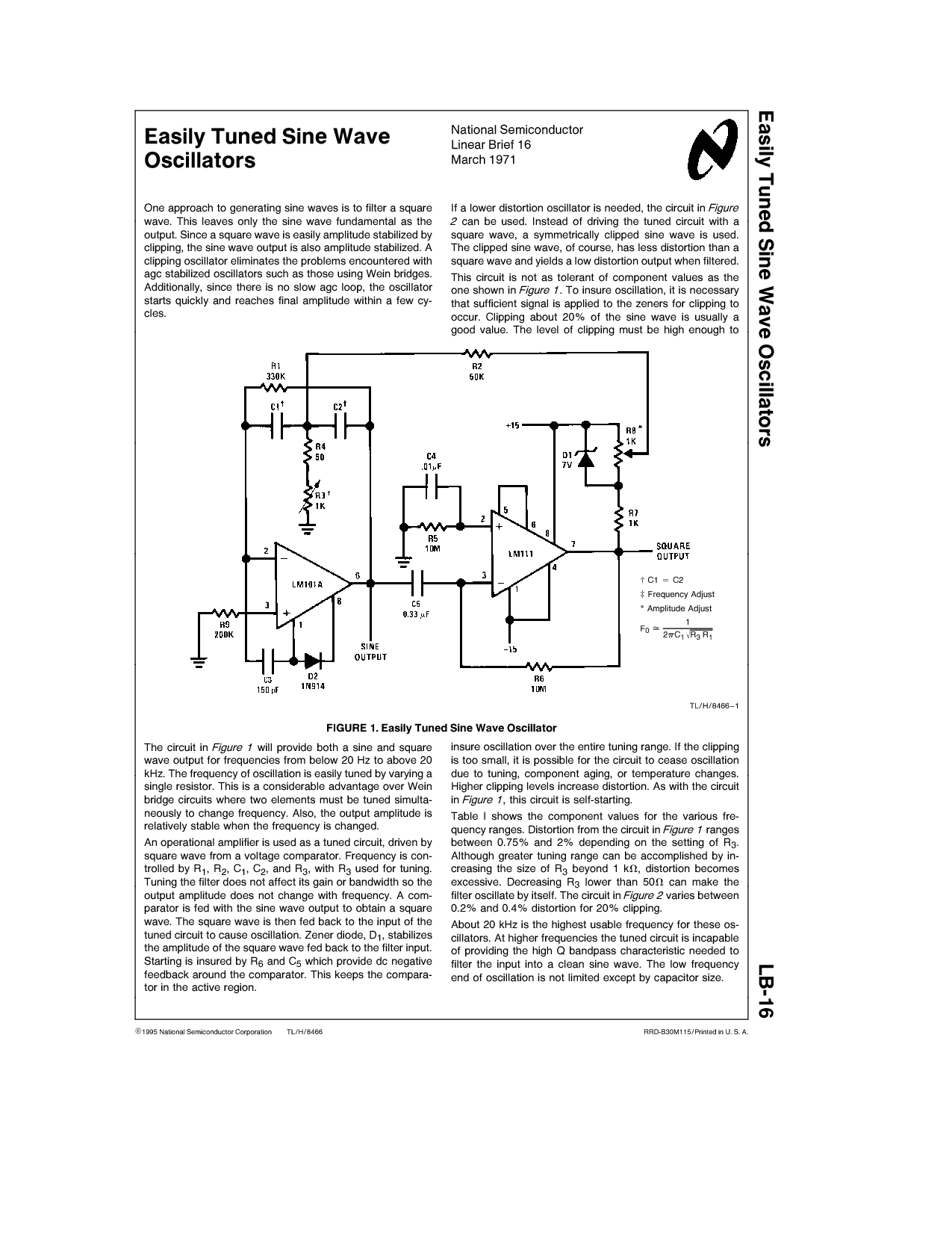
One approach to generating sine waves is to filter a square wave. This leaves only the sine wave fundamental as the output. If a lower distortion oscillator is needed, the circuit in Figure 2 can be used. Instead of...
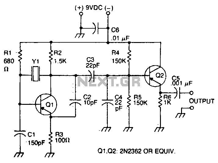
The oscillator transistor is Q1, and the crystal is placed between the collector and base. Feedback is improved by the use of the collector-emitter capacitor C2. Transistor Q2 is used as an output buffer. The circuit described features an oscillator...
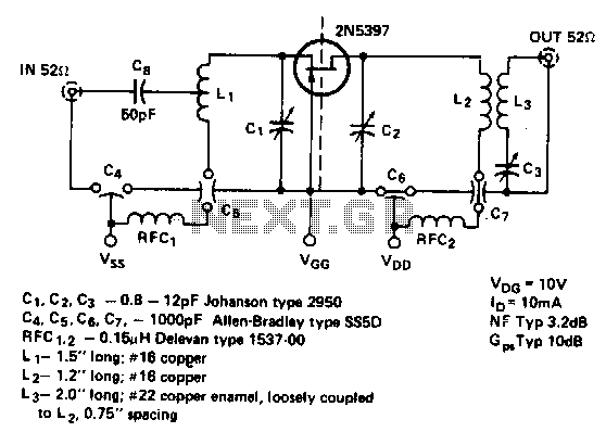
This is a low noise amplifier with a typical noise figure of 3 dB and approximately 10 dB of gain, operating within the frequency range of 450-470 MHz. It is designed for VHF two-way applications. The described low noise amplifier...
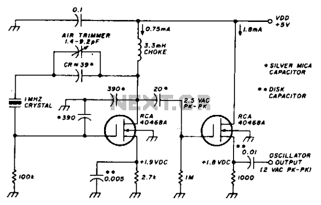
This stable oscillator circuit exhibits less than a 1 Hz frequency change over a VDD range of 3 to 9 volts. Stability is attributed to the use of MOSFET devices and stable capacitors. The described oscillator circuit is designed to...
Warning: include(partials/cookie-banner.php): Failed to open stream: Permission denied in /var/www/html/nextgr/view-circuit.php on line 713
Warning: include(): Failed opening 'partials/cookie-banner.php' for inclusion (include_path='.:/usr/share/php') in /var/www/html/nextgr/view-circuit.php on line 713