
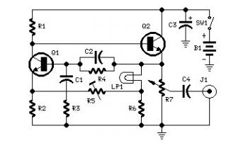
1KHZ Sine Wave Generator Circuit
An audio amplifier circuit typically consists of several key components, including resistors, capacitors, and the main amplification device, which in this case is the LM386 chip. The LM386 is a low-voltage audio power amplifier that is designed for battery-operated devices. It operates with a supply voltage ranging from 4V to 12V and can deliver up to 1 watt of output power into an 8-ohm load, making it suitable for small audio applications.
The circuit configuration often includes a gain-setting resistor connected between pins 1 and 8 of the LM386, allowing for adjustable amplification. For a standard gain of 20, no external components are needed; however, if higher gain is required, a resistor can be added. Bypass capacitors are also placed across the power supply pins to filter out noise and stabilize the voltage supply, improving the amplifier's performance.
Input signals are typically coupled to the amplifier through capacitors to block any DC offset, ensuring that only the AC audio signal is amplified. The output is connected to a speaker through an output capacitor, which blocks DC while allowing the amplified audio signal to pass through to the speaker.
In practical applications, this audio amplifier circuit can be used in a variety of settings, from personal audio systems to DIY projects. By following the schematic provided in the video tutorial, users can assemble the circuit on a breadboard or a PCB, making it an accessible project for those looking to enhance their audio capabilities without significant investment.Set R5 to read 1V RMS on an Audio Millivoltmeter connected to the output with R7 rotated fully clockwise, or to view a sinewave of 2. 828V Peak-to-Peak amplitude on the oscilloscope. An audio amplifier is an electronic amplifier that amplifies low-power audio signals (signals composed primarily of frequencies between 20 - 20 000 Hz, the human range
of hearing) to a level suitable for driving loudspeakers and is the final stage in a typical audio playback chain. The preceding stages in such a chain are low power audio amplifiers which perform tasks like pre-amplification, equalization, tone control, mixing/effects, or audio sources like record players, CD players, and cassette players.
Most audio amplifiers require these low-level inputs to adhere to line levels. While the input signal to an audio amplifier may measure only a few hundred microwatts, its output may be tens, hundreds, or thousands of watts. More explanation about power audio amplifier can be found at wikipedia. org This is a video tutorial about how to a very simple audio amplifier based on the LM386 amplifier chip.
It can be built for less than $20 (or might be less than $8 in some countries) and used to amplify any low level audio signal including a guitar, bass or mp3 player. 🔗 External reference
Related Circuits
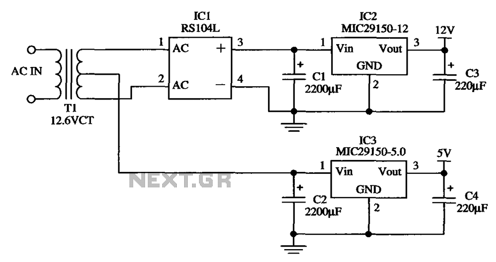
The low-cost dual output voltage regulator circuit is composed of two Micrel company regulators, the MIC29150-12 and the MIC29150-5.0. The dual output voltage regulator circuit utilizes the MIC29150 series from Micrel, which are low-dropout (LDO) voltage regulators designed for various...
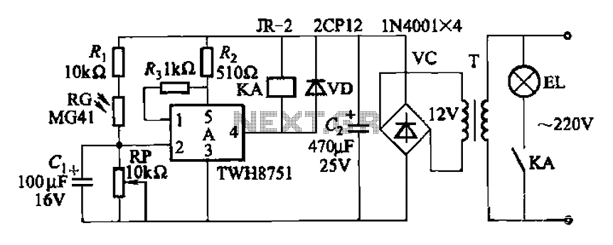
The adjustment potentiometer RP can modify the sensitivity of the device. Capacitors C1 function as an anti-light interference mechanism for instantaneous action. The adjustment potentiometer (RP) is a variable resistor that allows for fine-tuning of the device's sensitivity. By altering...
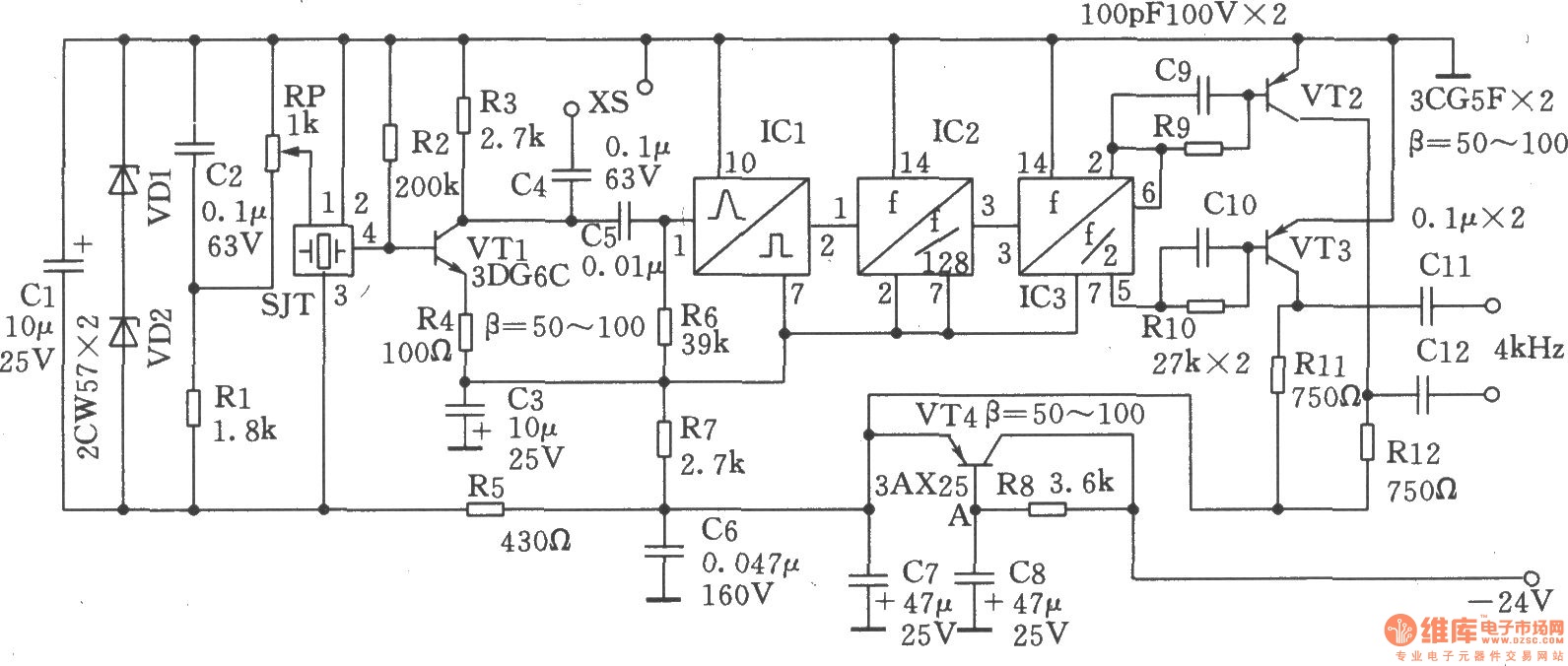
The circuit SJT is a 1024 kHz warming crystal oscillator. The circuit is illustrated in the accompanying chart. Due to the low output signal level, a transistor (VT1) is employed as a buffer amplifier. The base bias resistor (R2)...
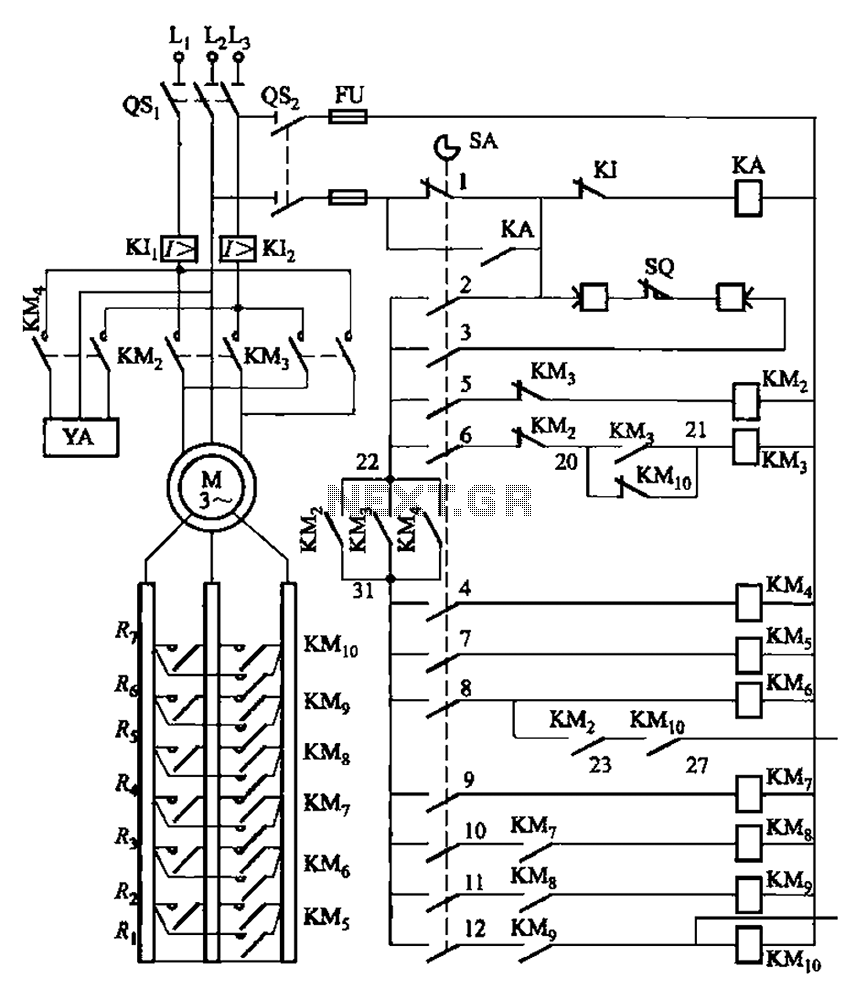
The system is managed by the master controller LKl-12/90 and a magnetic disk control unit PQR10A, which includes a control circuit. The cam control device SA is responsible for contact closure, as indicated in Table 8-5. The main electrical...
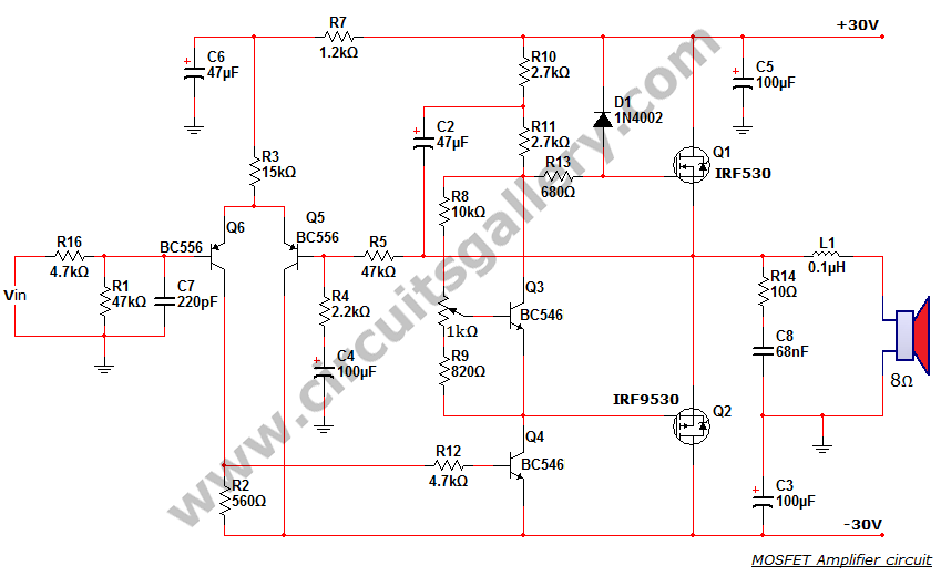
This is a MOSFET transistor-based power amplifier circuit that operates within a voltage range of +35V to -35V. The input voltage is pre-filtered and pre-amplified before being applied to the MOSFET switch. The pre-audio amplifier consists of a differential...
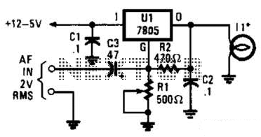
In the visible-light transmitter, a 7805 voltage regulator is configured in a variable-voltage setup, with an audio signal input to modulate the output voltage. The modulated output voltage is utilized to transmit information through an incandescent lamp. The visible-light transmitter...