
1MHz PIERCE OSCILLATORS
The Pierce oscillator is a type of crystal oscillator that utilizes a feedback loop to generate oscillations. It typically consists of a crystal, a transistor (or a combination of transistors), and passive components such as resistors and capacitors. The unique aspect of the Pierce circuit is its ability to operate efficiently at various frequencies, particularly around 1 MHz in this context.
When the crystal is operated slightly above its resonant frequency, the circuit can achieve stable oscillation with minimal complexity, requiring only a single high-gain transistor. This configuration is advantageous for applications where simplicity and space-saving are paramount. The high-gain transistor amplifies the signal, ensuring that the oscillation continues without the need for additional components.
Conversely, when the crystal is operated at its exact series resonance, the configuration demands an additional RC phase lag network and a second transistor. This adjustment is necessary to maintain the phase condition required for sustained oscillation, as the feedback loop must provide a total phase shift of 360 degrees (or 0 degrees) to ensure that the output is in phase with the input. The introduction of a second transistor allows for lower gain transistors to be used, which can be beneficial in applications where power consumption is a concern.
The choice of using a single or dual transistor configuration ultimately depends on the specific requirements of the application, including frequency stability, power consumption, and circuit complexity. The Pierce circuit's versatility makes it suitable for a wide range of applications in frequency generation, timing circuits, and signal processing, where precise frequency control is essential.Simple network design is a key feature of the Pierce circuit, as these 1-MHz oscillators illustrate.Operating the crystal slightly above resonance (Fig.21-5a) requires only one high-gain transistor stage.Operating it exactly at series resonance (Fig. 21-5b) requires an extra RC phase lag and two transistors which can have lower gain.. 🔗 External reference
Related Circuits
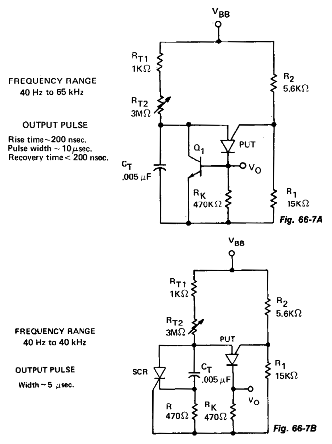
The variable oscillator circuit incorporates active components to discharge the timing capacitor CT, as illustrated in Fig. 66-7A. An alternative method is presented in Fig. 66-7B. The variable oscillator circuit is designed to generate oscillating signals with adjustable frequency characteristics....
The HV732 is a complete, high-speed, high-voltage ultrasound transmitter pulser. This high-performance CMOS integrated circuit (IC) is housed in a single 7x7x0.9 mm 44-lead multi-die QFN package. The HV732 can deliver up to ±2A source and sink current to...
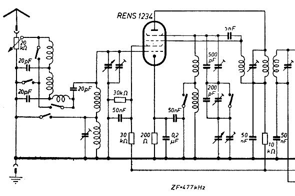
The schematic of the mixer section illustrates an oscillator. The oscillator's LC circuit has only two connections to the valve and does not include a tap or tickler coil. Oscillations will only occur if the tube provides a negative...
This circuit is a frequency meter, low cost. It covers region 1HZ until 1MHZ. The IC1 schmitt trigger that it regulates the signal of entry and him changes in reasonable level suitable for the IC2-3-4. With the tenth pulse...
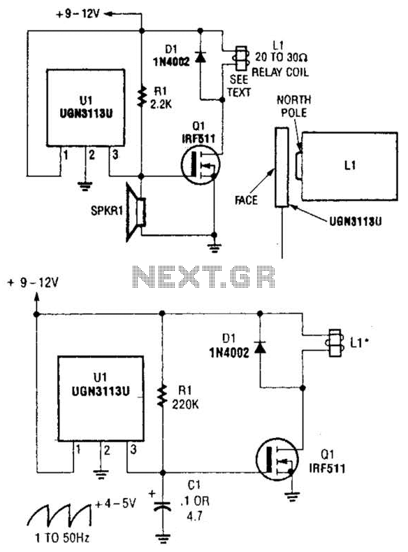
Although not intended for this application, a Hall-effect switch can be utilized as the foundation for an unconventional oscillator. The oscillator can be reconfigured, as illustrated in Fig. B, to enable the circuit's oscillating frequency to be regulated through...
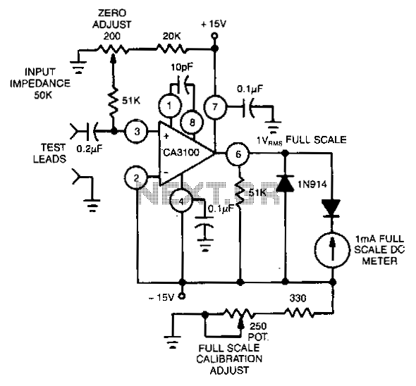
This circuit utilizes the CA3100 BiMOS operational amplifier to drive a 1-mA meter movement to its full scale with a 1-V RMS input. The circuit configuration incorporates the CA3100 BiMOS operational amplifier, which is known for its high input impedance...