
1watt AM/CW 10-meter band transmitter
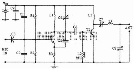
The described circuit is a low-power AM transmitter that operates in three stages, incorporating a crystal oscillator, a modulator, and an amplifier. The use of a crystal oscillator integrated circuit ensures stable frequency generation, which is crucial for maintaining clear signal transmission over the AM band.
The first stage consists of the crystal oscillator, which generates a carrier frequency. This frequency is determined by the crystal's specifications and is typically in the range of 530 kHz to 1700 kHz, which is the AM broadcast band. The output of this oscillator is then fed into the second stage, which is a collector modulated AM oscillator. This stage modulates the carrier signal with audio input from a microphone.
An electret microphone is preferred for this application due to its sufficient output voltage (at least 100 mV), which is necessary for effective modulation. If a dynamic microphone is used, a low-frequency preamplifier stage, typically utilizing a single transistor, can be added to boost the microphone's output to the required level. This preamp stage enhances the signal before it reaches the modulator, ensuring that the audio is adequately represented in the transmitted signal.
The final stage of the circuit is an amplifier that increases the power of the modulated signal. This stage is crucial for broadcasting the signal over a distance, allowing it to be picked up by standard AM radio receivers. The amplifier should be designed to match the characteristics of the modulated signal while providing sufficient power to ensure effective transmission.
Overall, this simple circuit allows for experimentation with AM transmission and reception, providing insight into the fundamental principles of radio communication. While more complex circuits are used in professional AM broadcasting, this project serves as an educational tool to understand the basics of amplitude modulation and radio frequency transmission.In this project, you will make a simple 3-stage low-power broadcast-type circuit, using a crystal oscillator integrated circuit and an a collector modulated AM oscillator with amplifier. You can connect the circuit to the an electred microphone or amplified dynamic microphone. Using an electred microphone is shown (in gray) in the diagram below. (no amplified dynamic microphone has a to low output voltage to work. at least 100mv is needed). You could also add a LF preamp stage of one transistor to allow connecting a dynamic microphone directly.
You`ll see that you can receive the signal through the air with almost any AM radio receiver. Although the circuits used in radio stations for AM receiving are far more complicated, this nevertheless gives a basic idea of the concept behind a princip 🔗 External reference
Related Circuits
The circuit amplifier and attenuator control video detector consists of a composition for the synchronization channel. The synchronization interval is where the gain circuit is increased. The described circuit involves an amplifier and an attenuator that work together to control...
The old common-base audio preamp, which has a noise figure of 5 dB, is a clear candidate for improvement in noise performance. A common-emitter configuration with shunt feedback provides an input resistance of 50 ohms, which is preferred by...
The following diagram illustrates an FM transmitter circuit capable of FM transmission up to 4W. The voltage supply for this circuit ranges from 12V to 16V, with a current consumption between 100mA and 400mA. This circuit operates within an...
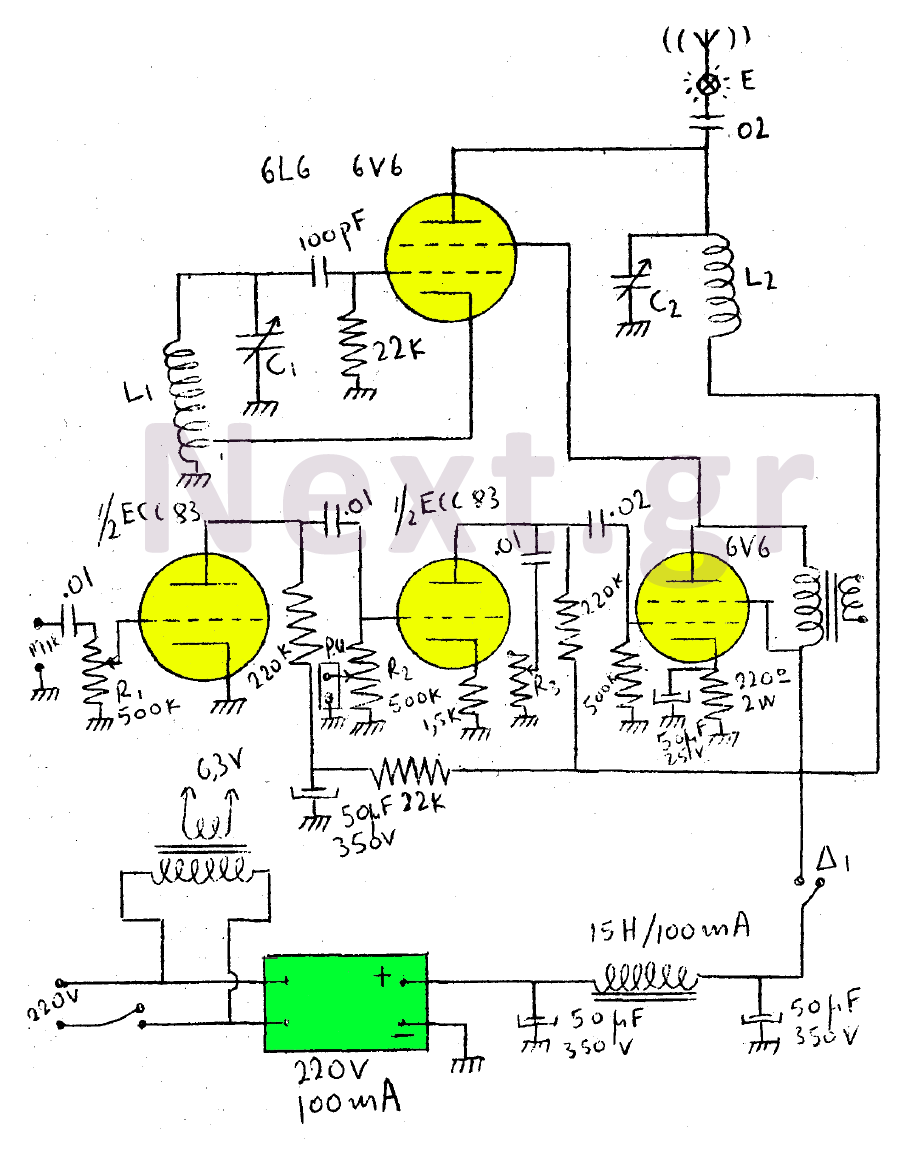
This circuit features a wearer assembly that includes a single lamp, either a 6V6 or 6L6, functioning as both an oscillator and an output amplifier. Coil L1 serves as the medium wave oscillation coil, while coil L2 is composed...
This transmitter was designed from the ground up to provide very high sound quality, coupled with excellent frequency stability, reliability, etc. It can be used as a standalone transmitter to serve a medium-sized town, or as an exciter to...
The regenerative detector uses a field effect transistor (FET). Like with the better valve designs, feedback is controlled by a variable capacitor. A ferrite rod was used to allow reception of local stations without an external antenna. This FET...
Warning: include(partials/cookie-banner.php): Failed to open stream: Permission denied in /var/www/html/nextgr/view-circuit.php on line 713
Warning: include(): Failed opening 'partials/cookie-banner.php' for inclusion (include_path='.:/usr/share/php') in /var/www/html/nextgr/view-circuit.php on line 713