
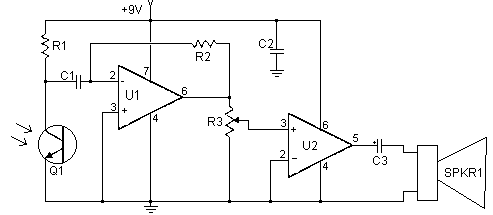
2 km FM transmitter
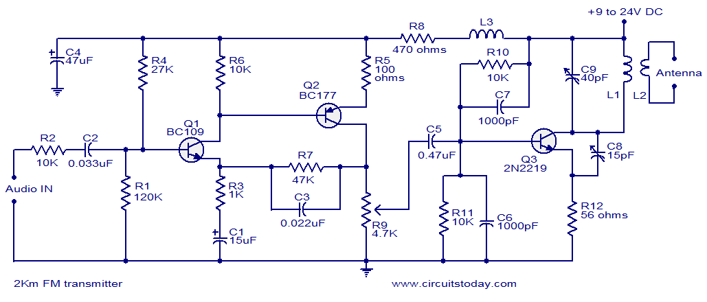
The FM transmitter circuit operates by utilizing a combination of transistors and passive components to achieve signal amplification and modulation. The input audio signal is fed into the preamplifier stage, where Q1 and Q2 amplify the signal. The coupling capacitor C2 ensures that only the AC audio signal reaches the base of Q1 while blocking any DC components that could affect the biasing of the transistor.
The biasing resistors (R1, R3, R4, R5, R6, and R9) are critical for setting the operating point of the transistors, ensuring they function efficiently within their active region. The calculated values of these resistors must be chosen carefully to avoid distortion in the transmitted audio signal.
The oscillator, mixer, and power amplifier functionalities are integrated into transistor Q3. This transistor modulates the amplified audio signal onto a high-frequency carrier wave, which is determined by the tank circuit formed by capacitor C9 and inductor L1. The resonant frequency of this tank circuit is essential for ensuring that the transmitter operates within the FM broadcast band (typically 88 to 108 MHz).
Inductor L2 plays a crucial role in coupling the modulated signal to the antenna, allowing the FM signal to be transmitted over the air. The design specifications for inductors L1 and L2 suggest using enamelled copper wire for durability and efficiency, with specific winding instructions to achieve the desired inductance values.
Proper grounding of the circuit is essential for minimizing noise and ensuring stable operation. The negative terminal of the power supply must be connected to the ground to provide a common reference point for all components.
In conclusion, the described FM transmitter circuit is capable of transmitting audio signals effectively over a distance of up to 2 kilometers, provided that it is constructed with high-quality components and proper attention is given to the layout and assembly of the circuit. To enhance performance and reduce noise, attention should also be paid to the selection of the antenna and the overall circuit design.With a matching antenna, the FM transmitter circuit shown here can transmit signals up to a range of 2 kilo meters. The transistor Q1 and Q2 forms a classic high sensitive preamplifier stage. The audio signal to be transmitted is coupled to the base of Q1 through capacitor C2. R1, R3, R4, R6, R5 and R9 are the biasing resistors for the preamplifie r stage comprising of Q1 and Q2. Transistor Q3 performs the collective job of oscillator, mixer and final power amplifier. C9 and L1 forms the tank circuit which is essential for creating oscillations. Inductor L2 couples the FM signal to the antenna. For L1 make 3 turns of 1mm enamelled copper wire on a 10mm diameter plastic former. On the same core make 2 turns of 1 mm enamelled copper wire close to L1 and that will be L2. Hello Sir, is this circuit has really more than 1 km range with good quality sound and very low noise i tried many different 2km FM transmitter circuit on internet but all of those can not go even 150 meter and also full of noise. so i am afraid. PLEASE HELP ME TO INFORM ME ABOUT THIS CIRCUIT Hi Naren you can use any RH Choke in this place. you can wind around 24 turns of 22swg enemelled copper close wound on 6mm dia self supporting, without any core material(air core)you can wind on a pencil slideout and use.
SIR I AM LAXMAN I WANT MAKE A 2KM FM TRANSMITTER. I HAVE SEEN THE CIRCUIT BUT I AM NOT UNDERSTAND WHAT IS L3 THIS IS A COIL AND WHAT IS C9 40PF AND C815PF. THESE ARE PRE SET THIS IS AVALIABLE IN MARKET AND WHAT IS CALL IN MARKET. The negative of the supply should be connected to common line shown as connected to ground. All your components are ok except choke. See my earlier comment. (Hi venkatesh it is an rf choke to prevent rf entering the audio amp stage through power supply. any choke around 200 to 500uH will do. it is normally aircored with 200 to 300 turns honey comb winding to 5mm width with an ID of 6 to 10mm.
) I have successfully made the transmitter and I want to say a big thank you to you . I now want another help from you in making a long distance (above 3km in distance) . Please help me send the detail to my e-mail address . salami_azeez0619@yahoo. com Please Plz tell me! spose I have made a very basic FM TRANSMITTER having a 100 meter of rang. Now my question is that is every Fm radio receiver can recieve my voice, witch is transmitted by my FM TRANSMITTER at this rang. Plz tell me! spose I have made a very basic FM TRANSMITTER having a 100 meter of rang. Now my question is that is every Fm radio receiver can recieve my voice, witch is transmitted by my FM TRANSMITTER at this rang.
Reply me! ahsan_mehmood21@yahoo. com I need a 25watt fm transmitter. Can anyone give me a ready made fm transmitter. I`ll pay for it, just i want to buy a fm transmitter of 25 watt. I`m from bangladesh. My phone number:+8801719974170, email: imtiaz2580@yahoo. com Sir from where to get the 3. 5 turns variable coil that is need in IC BA 1404 stereo FM transmitter. Everything is there in my place nut only that 3. 5turns variable coil is not available yet. Its very very urgently need it pls help me my contact no is 8793388142 if you know about the availability in India. thanks you . Sir, i will want you to help me with a detailed Fm transmitter without omitting any detail from it. If i can even get more than 2Km as my distance. I am using it as my project and my school are planning to have a Radio station for the school to broadcast in the campus area.
I will be glad if u make them recognize me, since i recognize you as a mentor. I have once built more than 4-perfect 200m Fm transmitter through you. Thanks sir. U are always impressing. Thirdly, can one use two of the type of antenna used in radio receivers folded in L shape with one end connected to the output and the other connected to the earth of the circuit, but there would be close to each other Thirdly, can one use two of the type of antenna used in radio receivers folded in L shape with one end connected to the output and the other connected to the earth of the circuit, but there would be close to each other Hi Raspol Your ideas are fine. with Ham Licence you can be on 144MHz FM band not on broadcast bands 88 to 108MHz. For walkie talkies use in India, you have to get licence from Department of Wireless communication, New Delhi (now regional offices for wireless monitoring are also there at various locations, you can contact wireless inspector available for guidelines).
(the application contains all the required data like location, antenna height, radiated power output, nearest airport etc) You will be allotted one frequency and also the place of operation, based on that you have to place order with walkie talkie companies and buy a suitable handset/base station and inform ministry accordingly. The present cost may be around INR1200 annual licence fee per set. However, my use of the transmitter is for a 45 minutes to 1 hour daily spiritual speech. What do I intend to use it for I want to help the people who aren`t able to come to listen to the spiritual speech, over their FM radio, using an FM transmitter.
My question is, if I get a HAM radio license, can I use this kind of transmitter for daily (early morning) use for about an hour Or are there any other ways that I can use this kind of transmitter for daily use My other question is regarding walkie talkies. Many models from Motorola are available from ebay these days. Can we use such walkie talkies during times when phones won`t work or during emergencies i observe after operation the frequency changes and as i use it how many times, the how many times also change.
from 101. 6Mhz, now it`s 99MHz. My instructor told me that using crystal oscillator would be better and maintain the stability of the operating frequency. How can i do or connect it if possible and i also observe that as i increase the gain from 1/3 to 1 cycle of the potentiometer, it creates noise.
i already reduce the input audio voltage as little in that case thinking that would be an over modulation only but still has noise. is there something wrong with my variable resistor using 5Kohms instead of 4. 7Kohms or its just because what i have are local componennts Hi Kosovari there is no polarity for ceramic capacitors.
it is non polar. The value is similar to resistance color code instead of color numerals are given. 102 means 10 X 10 to the power 2. that is 1000PF. 222 is 22 X 100 = 2200PF. 🔗 External reference
Related Circuits
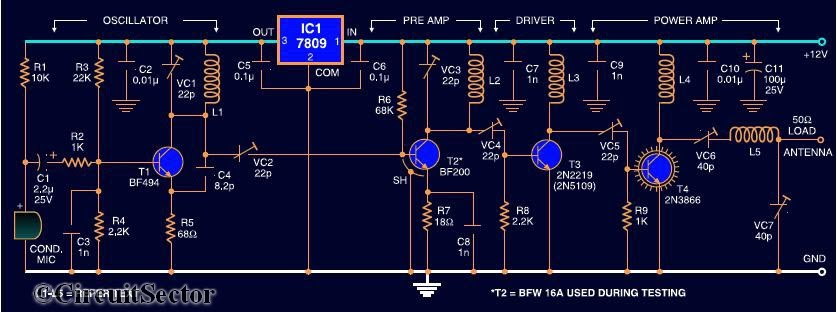
Here is the circuit diagram of a four RF stage FM transmitter. The stages include a very high frequency (VHF) oscillator built around the HF transistor BF494, a pre-amplifier using the BF200 transistor, a driver transistor 2N2219, and a...
The circuit includes a comprehensive array of components such as vibration sensors, a follower, a lamp relay control circuit, a voice sounding circuit, a high-frequency oscillation circuit, and an AC rectifier buck power supply circuit. The vibration sensor is...
The camera is oriented to look out the side of the rocket during launch and downward during descent on the parachute. An optional external mirror can be added to enable the camera to look down during lift-off. The transmitter...
This set of two circuits forms the basis for a very simple light wave transmitter. A LASER beam is modulated and then aimed at a receiver that demodulates the signal and then presents the information (voice, data, etc.). The...
This is likely the simplest radio transmitter available, consisting of five components and capable of being assembled in a compact space. It is suitable for science fair projects or other science-related endeavors where short-range transmission is beneficial. The device...

Most consumer electronic devices utilize infrared remote controls for convenient operation. The carrier frequency of these remote controls typically ranges from 36 kHz to 38 kHz. Control codes are transmitted to the device's receiver in a serial format, which...
Warning: include(partials/cookie-banner.php): Failed to open stream: Permission denied in /var/www/html/nextgr/view-circuit.php on line 713
Warning: include(): Failed opening 'partials/cookie-banner.php' for inclusion (include_path='.:/usr/share/php') in /var/www/html/nextgr/view-circuit.php on line 713