
2 LED CMOS Flasher
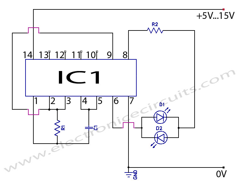
The two LED CMOS flasher circuit utilizes the CD4069 integrated circuit, which contains six inverters, to create a multivibrator configuration. This circuit is designed to flash two LEDs alternately, providing a visual indication of the oscillation created by the inverter gates.
In this configuration, two of the six inverters are employed to form a basic astable multivibrator. The circuit operates by charging and discharging capacitors, which control the timing of the LED flashes. The LEDs are connected to the output of the inverters, allowing them to turn on and off in succession.
The key components of the circuit include:
1. **CD4069 IC**: This is a hex inverter that provides the necessary logic levels for the multivibrator operation.
2. **Resistors**: Used to limit current to the LEDs and to set the charging and discharging time constants for the capacitors.
3. **Capacitors**: These components are crucial for determining the frequency of the flashing LEDs by controlling the timing intervals.
4. **LEDs**: Light Emitting Diodes that visually indicate the output states of the circuit.
The circuit is powered by a DC voltage source, typically ranging from 3V to 15V, depending on the specifications of the LEDs and the CD4069. The values of the resistors and capacitors can be adjusted to change the frequency of the flashing LEDs, allowing for customization of the visual output.
Overall, this simple yet effective circuit serves as an excellent introduction to basic CMOS technology and multivibrator design, demonstrating fundamental principles of electronics in a practical application.Two LED CMOS Flasher Circuit Diagram This is a simple 2 led cmos robot ( flasher, multivibrator ) circuit using CD4069 six inverter.. 🔗 External reference
Related Circuits
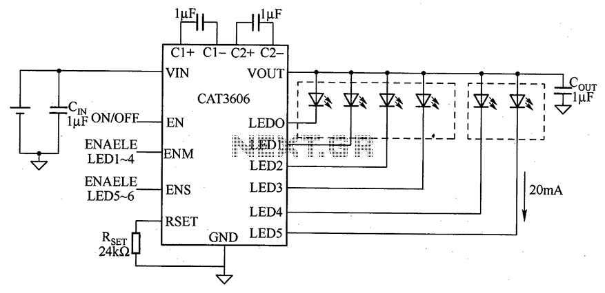
CAT3606 is a high-efficiency white LED driver. This adjustable charge pump is suitable for general-purpose, large-panel, flicker-free white LED backlighting and dual-display systems. The CAT3606 inductor boost circuit can replace conventional high-brightness backlighting requirements, thereby simplifying system design. It...
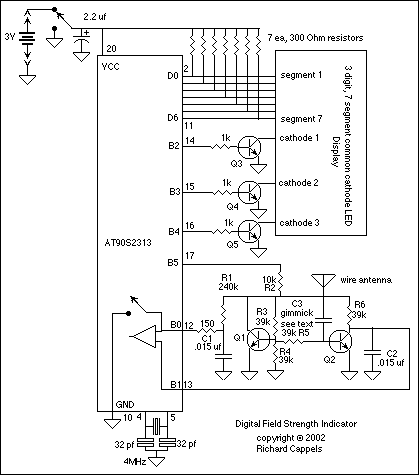
Useful as a transmitter tune-up meter or an RF sniffer, this is an RF field strength indicator that is loosely based on the Broad Band RF Field Strength Probe, described elsewhere. It detects RF via a square law detector,...
There is no prior experience in building controllers, and there is uncertainty about how to begin. A budget constraint of less than 100 euros is present. A power thyristor is already available. The inquiry revolves around the best method...
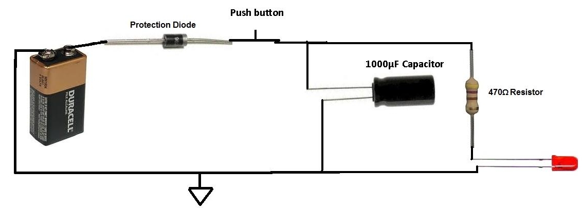
This project involves charging a capacitor with voltage, which will subsequently serve as a temporary power source for the circuit. After charging the capacitor with a battery, the battery is disconnected from the circuit. The capacitor then provides current...
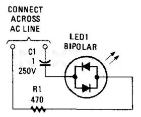
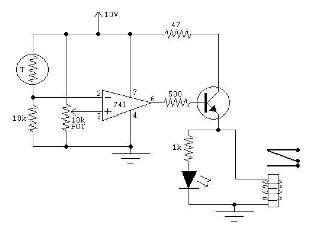
Many electronic circuits require an indication that they are powered. For most AC circuits, a neon lamp is the preferred device. A bidirectional tricolor LED can also be utilized if a capacitor is connected in series with the LED...
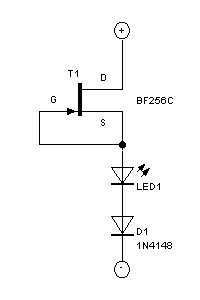
This circuit uses the effect of a FET as the power to act through the gate with the source to connect. The voltage may vary between 4V and 30V, the current through the LED should constantly be around 15mA....
Warning: include(partials/cookie-banner.php): Failed to open stream: Permission denied in /var/www/html/nextgr/view-circuit.php on line 713
Warning: include(): Failed opening 'partials/cookie-banner.php' for inclusion (include_path='.:/usr/share/php') in /var/www/html/nextgr/view-circuit.php on line 713