
2 line intercom plus a telephone changeover switch
The circuit design incorporates a robust intercom system that allows seamless communication between two telephones while maintaining the functionality of a third telephone connected to the main exchange line. The implementation of a 3-pole, 2-way slide switch (S3) is crucial for managing the changeover between intercom and exchange line modes. This switch not only facilitates the routing of calls but also ensures that the power supply to the telephones is effectively controlled to prevent interference.
In the intercom mode, the buzzer (PZ2) serves as an alert mechanism, signaling the initiation of a conversation. The side tone feature enhances the user experience by providing auditory feedback to the person using telephone 1, indicating that the communication line is active. The design ensures that both telephones in intercom mode can communicate without the risk of cross-talk or interference from the exchange line, thus preserving privacy.
The circuit's operation is contingent on the proper toggling of switch S3. When switched to the changeover position, the supply voltage to telephones 1 and 3 is cut off, preventing them from ringing or being active during the call on telephone 2. This design consideration is critical for maintaining the integrity of the exchange line connection while allowing for intercom functionality.
Furthermore, the ring-tone-sensing unit remains functional even after the changeover, providing feedback to the user of telephone 3 regarding incoming calls. This feature is particularly advantageous, as it keeps the user informed of call activity without compromising the primary function of the intercom system.
In summary, this circuit design effectively addresses the common challenges associated with parallel telephone line connections by integrating intercom functionality with a changeover mechanism, ensuring both privacy and operational efficiency.Usually a single telephone is connected to a telephone line. If another telephone is required at some distance, a parallel line is taken for connecting the other telephone. In this simple parallel line operation, the main problem is loss of privacy besides interference from the other phone.
This problem is obviated in the circuit presented here. U nder normal condition, two telephones (telephone 1 and 2) can be used as intercom while telephone 3 is connected to the lines from exchange. In changeover mode, exchange line is disconnected from telephone 3 and gets connected to telephone 2.
For operation in intercom mode, one has to just lift the handset of phone 1 and then press switch S1. As a result, buzzer PZ2 sounds. Simultaneously, the side tone is heard in the speaker of handset of phone 1. The person at phone 2 could then lift the handset and start conversation. Similar procedure is to be followed for initiation of the conversation from phone 2 using switch S2. In this mode of operation, a 3-pole, 2-way slide-switch S3 is to be used as shown in the figure. In the changeover mode of operation, switch S3 is used to changeover the telephone line for use by telephone 2.
The switch is normally in the intercom mode and telephone 3 is connected to the exchange line. Before changing over the exchange line to telephone 2, the person at telephone 1 may inform the person at telephone 2 (in the intercom mode) that he is going to changeover the line for use by him (the person at telephone 2). As soon as changeover switch S3 is flipped to the other position, 12V supply is cut off and telephones 1 and 3 do not get any voltage or ring via the ring-tone-sensing unit.
Once switch S3 is flipped over for use of exchange line by the person at telephone 2, and the same (switch S3) is not flipped back to normal position after a telephone call is over, the next telephone call via exchange lines will go to telephone 2 only and the ring-tone-sensing circuit will still work. This enables the person at phone 3 to know that a call has gone through. If the handset of telephone 3 is lifted, it is found to be dead. To make telephone 3 again active, switch S3 should be changed over to its normal position. 🔗 External reference
Related Circuits
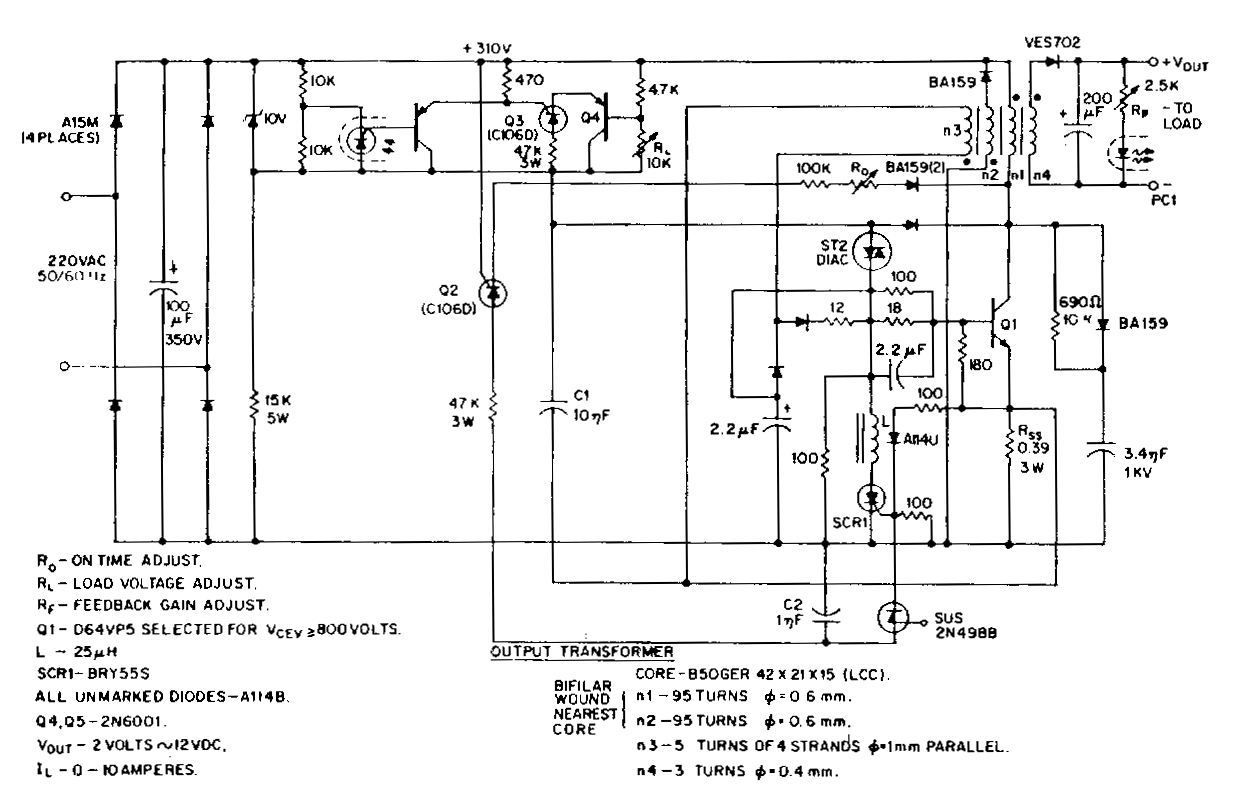
This low-voltage, high-current output switching power supply operates from a 220 VAC input. In this circuit, an ST2 diac relaxation oscillator, along with Q3, C1, and the diac, initiates the conduction of the output switching transistor Q1. The on-time...
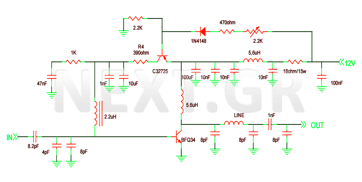
This project involves the construction of a VHF-UHF linear amplifier capable of operating at frequencies ranging from 47 MHz to 740 MHz. It serves as the final output stage for any transmitter functioning within these frequencies. The amplifier utilizes...
This is a 220V touch switch circuit. This circuit functions as a switch that turns off and on the electronic device connected to the 220V home supply. The 220V touch switch circuit is designed to control the operation of electrical...
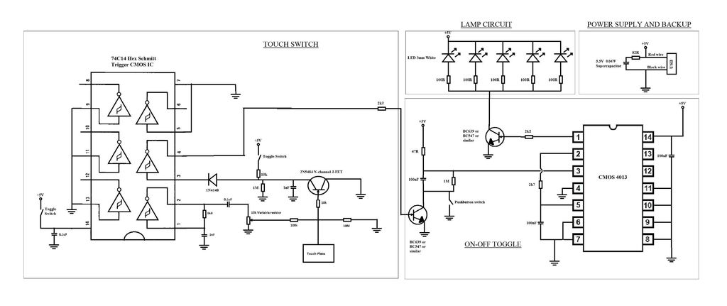
A touch switch for a USB-powered desk lamp is malfunctioning. The circuit diagram, layout, and pictures are provided below. The design incorporates circuits sourced from two websites, specifically the fourth circuit. The output of the touch switch is connected...
This circuit is an ultra-sensitive infrared (IR) receiver designed to control various AC devices via an IR transmitter. It utilizes a phototransistor... The ultra-sensitive IR receiver circuit is engineered to detect infrared signals emitted from an IR transmitter, enabling the...
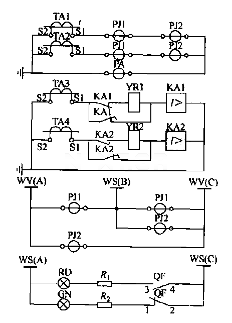
Expanding schematic circuit for the secondary circuit of high-voltage lines. The schematic circuit for the secondary circuit of high-voltage lines is designed to enhance the distribution and management of electrical power in high-voltage systems. This circuit typically includes components...
Warning: include(partials/cookie-banner.php): Failed to open stream: Permission denied in /var/www/html/nextgr/view-circuit.php on line 713
Warning: include(): Failed opening 'partials/cookie-banner.php' for inclusion (include_path='.:/usr/share/php') in /var/www/html/nextgr/view-circuit.php on line 713