
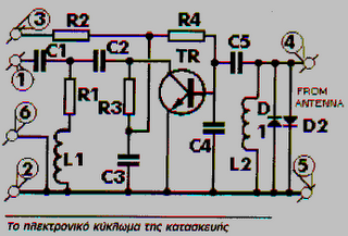
2 x 22W-BTL Car Audio Amplifier DA1553CQ Schematic Diagram
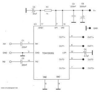
The circuit design for the 22-watt car audio amplifier utilizing the TDA1553CQ integrates several critical components to ensure optimal performance in automotive environments. The TDA1553CQ is a dual-channel amplifier capable of delivering 22 watts per channel into a load of 4 ohms, making it suitable for driving car speakers effectively. The differential input stage enhances noise immunity, which is essential in the electrically noisy environment of a vehicle.
The gain of 26 dB is fixed, providing a consistent amplification level for audio signals, which simplifies system design and integration. The amplifier's architecture includes a built-in thermal protection mechanism, which is crucial for preventing damage due to overheating during extended use or under high load conditions.
In the event of a short circuit at the output, the protection circuit is automatically engaged. This circuit monitors the voltage across the loudspeaker and limits it to a safe level, thus preventing potential damage to both the amplifier and the connected speaker. The diagnostic feature on pin 12 allows for monitoring and troubleshooting of the amplifier's status, making maintenance easier.
The circuit is designed to operate efficiently with minimal power consumption, as indicated by the reduced supply current during fault conditions. This characteristic is particularly beneficial in automotive applications, where power efficiency is a priority.
Overall, the 22-watt car audio amplifier based on the TDA1553CQ is a robust solution for enhancing audio performance in vehicles, combining effective amplification with essential protection features to ensure reliability and longevity in automotive audio systems.This is a 22 Watt car stereo audio amplifier. The circuit is based by a single IC TDA1553 with a few peripheral components, this IC hope against hope code name your stereo car audio classification. The IC TDA1553CQ contains 2G—22 W amplifiers with differential input stages and can exist used in favor of connection applications.
The expansion of ap iece amplifier is fixed by the side of 26 dB. The device is primarily residential for car broadcasting applications. What time a diminutive-circuit to ground occurs, which forces a DC voltage across the loudspeaker of >= vs. , a built-in protection circuit becomes full of life and limits the DC voltage across the loudspeaker to <= vs.
Pin 12 detects the status of the protection circuit (e. g. meant for diagnostic purposes). If slightly output is unfriendly-circuited to ground in the course of the side with mode, it becomes hopeless to switch the circuit to the mute otherwise operating condition. happening this event the supply current determination remain some degree of to a little milliamps. You are reading the Circuits of 2 x 22W-BTL Car Audio Amplifier DA1553CQ And this circuit permalink url it is
🔗 External reference
Related Circuits
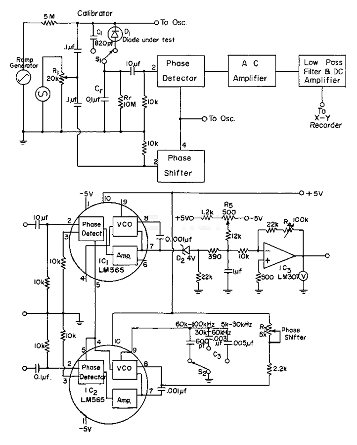
The application of automatic plotters for measuring the capacitance-voltage characteristics of solar Schottky gate diodes is discussed. A diode is connected as illustrated below. The integrated circuit (IC) generates a square wave output phase. Additionally, resistor R3 can be...
The project utilizes a 10 x 20 grid of RGB LEDs controlled by the myRIO. It is operated through a web interface on any device that supports WebSockets. Originally, the system was built using an Arduino, but the creator...

During the recent audio hackers meetup at Hacker Dojo, discussions were held with Laura and Kevin regarding the challenges faced in creating a small local network referred to as "JamLan." There was mention of the consideration to develop a...
A Class A Class AB amplifier rated 100 Watts when driving a 4 ohm loudspeaker. This circuit developed out of my 30+ years of JLH class-A based investigations. The original simple 1969 JLH class-A design provided excellent first cycle accuracy...
These frequencies include TV in VHF and UHF, as well as the radio broadcasting frequencies in the 88 - 108 MHz FM band. Component: Resistor, IC. The circuit described operates within the VHF (Very High Frequency) and UHF (Ultra High...
Graphic equalizers consist of 15 or 30 band-pass filters, each corresponding to a 1/3 octave frequency. Traditional equalizer designs utilize standard discrete components to implement these band-pass filters. The Apex GX and PE series have demonstrated superior performance by...