
2004 chevy impala: relay diagram passenger side fuse block
The 2004 Chevrolet Impala's electrical system includes various components that may affect the operation of the rear defogger. The rear defogger circuit typically includes a relay, fuse, and circuit breaker, all of which play crucial roles in ensuring proper functionality. The relay serves as an electronic switch that activates the defogger when the driver engages the defrost switch, while the fuse protects the circuit from overloads. The circuit breaker, located within the junction box, is designed to reset itself after tripping, providing additional protection.
To troubleshoot the rear defogger issue, it is essential to verify that the BCM is sending the appropriate signals. This can be done by checking for voltage at the relay's input terminals while the ignition is on and the defrost function is activated. If no voltage is detected, further investigation into the BCM or associated wiring may be necessary.
The absence of the 30-amp fuse raises the possibility of a wiring fault or a malfunctioning circuit breaker. The dark green wire, presumed to be the power feed, should be traced from the junction box to ensure continuity and that no breaks or shorts exist. If the circuit breaker is suspected to be faulty, it should be inspected for damage or tripping.
Accessing the circuit breaker may require removing the glove box or other components to reach the junction box's backside. Care should be taken during this process to avoid damaging any surrounding parts. If the circuit breaker is confirmed to be operational, further examination of the wiring harness and connections leading to the rear defogger may be warranted to identify any potential issues.2004 chev impala - unable to find the fuse for the rear defogger. I find the relay but both manual and actaul car diagram and passenger side fuse block show 30amp fuse - but nothing is there. Thanks, I check that fuse and it is OK. I see there is a circuit breaker on the schematics. This car does have A/C does that mean the right side (A/C) of dia gram is the one to use I replaced the relay - still no clicking in relay when I turn on switch ( no power at leads in back as well). Also, compressor clutch broke early in summer - I did not repair - can there be a tie in with this YES.
it is possible. You are going to want to check for 2 powers going into the defogger relay with the key on and switch defrost pressed. THis will ensure that the BCM is sending a signal to the relay and that the complete other side of the circuit is ok.
With car running - full voltage to two circuits. If your are sure there is no 30 amp circuit - I will check for line problems between fuse box and back of car. what color is the hot coming out of the box I am assuming dark green = thicker gauge wire. THere is that 30 amp circuit breaker in the junction box that will trip and could allow for no power going to the grid.
Just keep that in mind. Maybe it is bad or maybe it is just tripped That is actually my original question - how do I find that breaker I t should be on passenger side - is it in back of the box take out the glove box or does the box come out The first diagram is the one I have in owner`s manual / on the junction box. It lists the 30 amp defooger breaker and the power seat breaker as "Inside Components". when I look at the junction box i see all of the breakers but these two "inside components". The right side of the junction box has a gray cover. i removed that. there is a whites grid with all the incoming or outgoing wires coming out. there is a screw in the middle of the white grid. i have unscrewed the screw - it does not come out all the way and the white grid is still attached. I did not want to place to much force to pull out the white grid. does the "inside component mean the circuit is under the white grid The diagram shows it comes off - is that a correct assumption Or is the breaker on the backside of the block which requires taking out the glove box ( still not sure i could get to it.
Are you able to see the previous stream of messages on this one It is not there - or at least not where I can find it - let me know if you can`t see the previous mechanics resposnes and questions. Have read all & if your 2004 Impala does NOT have the Circuit Breaker on the "RIGHT SIDE" of the Dash as shown, then it is only activated thru the BCM & powered as shown above from the Right Hand RELAY Ask-a-doc Web sites: If you`ve got a quick question, you can try to get an answer from sites that say they have various specialists on hand to give quick answers.
Justanswer. com. Traffic on JustAnswer rose 14 percent. and had nearly 400, 000 page views in 30 days. inquiries related to stress, high blood pressure, drinking and heart pain jumped 33 percent. 🔗 External reference
Related Circuits
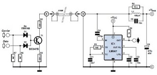
This circuit was designed to transmit commands over an LNB coaxial cable. An LNB (Low-Noise Block downconverter) is commonly used for satellite TV reception and is positioned at the focal point of a satellite dish. The circuit generates a...
To convert a standard LCD interface from parallel to a serial interface model, a microcontroller or a dedicated circuit such as the MIC 702 from Mictronics can be used. This circuit is specifically designed to transform the parallel interface...
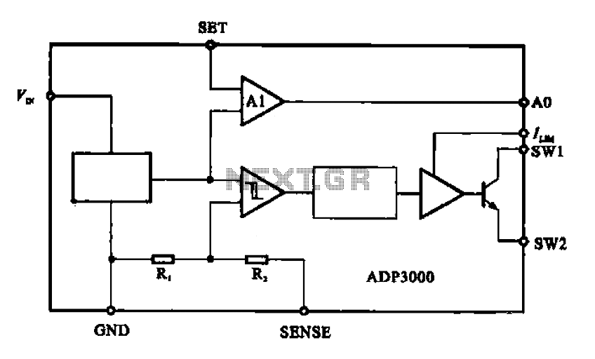
The ADP3000 is an integrated circuit featuring a block diagram that illustrates its internal structure as a high-frequency switching regulator. The ADP3000 integrated circuit is designed to provide efficient power management in various applications, particularly in systems requiring high-frequency switching...
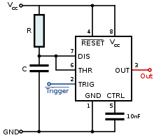
It can be assumed that most 555 timer chips from various manufacturers are interchangeable due to their similar pin configurations. However, the programs or diagrams may simplify the pin arrangements, leading to potential confusion. Custom routing may be necessary...
This circuit diagram illustrates the design of a straightforward AC voltage converter that transforms 240V AC power into 110V AC. The circuit can effectively be utilized to power electrical devices that necessitate a supply voltage of 110V. The AC voltage...
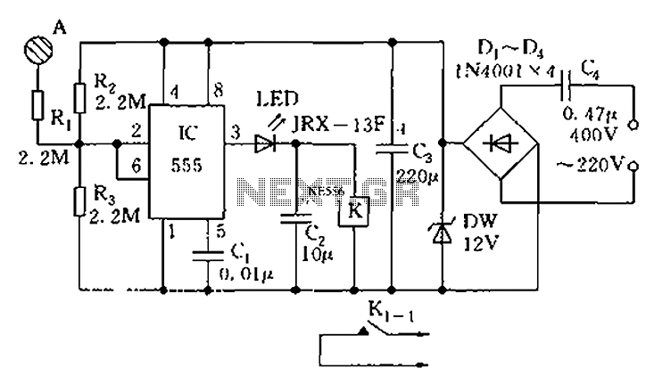
The touch sensor switch circuit diagram features a step-down rectifier circuit, a 555 timer, and flip-flops. When a hand touches the metal sheet A, the sensor signal activates the internal comparator of the 555 timer, setting the output to...
Warning: include(partials/cookie-banner.php): Failed to open stream: Permission denied in /var/www/html/nextgr/view-circuit.php on line 713
Warning: include(): Failed opening 'partials/cookie-banner.php' for inclusion (include_path='.:/usr/share/php') in /var/www/html/nextgr/view-circuit.php on line 713