
2011 Rife Beam Ray System

The Rife Beam-Ray system operates on the principles of frequency modulation and bioelectromagnetic therapy, utilizing specific frequencies that are theorized to resonate with biological systems. The control circuit logic is critical for ensuring that the modulation is accurately applied to the carrier frequency, thus allowing for effective transmission of the Rife frequencies. The choice of a Phanatron tube is significant due to its historical association with Rife's original experiments, providing a suitable medium for the application of the generated frequencies.
In the construction of the system, careful attention must be paid to the design of the matching network, which is essential for maximizing the transfer of energy from the RF amplifier to the Rife tube. This network is typically composed of reactive components such as capacitors and inductors, configured to match the impedance of the Rife tube, thereby minimizing reflections and losses. The implementation of a precision crystal-controlled oscillator ensures frequency stability, which is crucial for the efficacy of the therapy being administered.
The use of common consumer electronics, such as CD players or computers with sound cards, for generating the modulation frequencies is a notable aspect of the design. This approach not only reduces costs but also enhances accessibility for users who may not have advanced technical skills. The audio files used for the frequency sweep can be easily created or sourced from existing libraries, allowing for flexibility in the modulation parameters.
Overall, the Rife Beam-Ray system represents a fusion of historical principles and modern technology, aiming to provide an effective tool for exploring the potential benefits of frequency-based therapy in a user-friendly format. The detailed schematics and construction data serve as a valuable resource for individuals interested in building their own systems, promoting further exploration and experimentation in the field of bioelectromagnetic therapy.This document describes a Rife Beam-Ray system which was designed and constructed using the latest information available about Royal Rife`s actual frequencies. This system uses a novel method of generating the proper modulation frequency for the 3. 1 MHz carrier, and describes the design and operation of the control circuit logic required for that purpose. A method of coupling the power RF amplifier to the Rife Tube that eliminates the commonly used antenna tuner is described. Schematics and construction data are also provided. Since 1997 I have constructed several different types of Rife Beam-Ray systems. The earlier versions operated on the Bare-Rife principle, where a 27 MHz carrier was square-wave modulated by a sequential series of audio frequency signals.
After reviewing the currently available data from many researchers and experimenters, I decided to construct a system which would incorporate the latest frequency data findings as well as some of my own ideas which would allow me to simplify the construction and operation of the system, and make it easier for less technically skilled persons to assemble such a system. The first task was to determine exactly which carrier and modulation frequencies would likely be the most useful.
Please refer to the following documents that are located on the web site, . The pertinent documents are: for the how any why of it all. This page allows you to read each chapter on-line. If you prefer, the entire document may be downloaded as a large PDF file at:. The system has to perform several interrelated operations to be useful. First, it must be capable of generating the correct Rife frequencies. By using a 3. 1 MHz carrier combined with a separate 25, 000 to 500 Hz square wave modulation frequency, the correct frequencies may be generated. Second, the system must be able to get the frequencies into the biological system. This is done by using a Rife Beam-Ray tube, which may be either a Phanatron as Rife used, or a straight tube, with or without internal electrodes.
I decided to use a Phanatron tube for this system. This system follow much the same design, but with a few modifications to make it easier to operate. The often complex and expensive audio/function generator is replaced by a simple frequency which smoothly sweeps from 25, 000 Hz down to 500 Hz over a period of roughly four hours, or some other time period as set by the operator. To produce this sweep frequency, a common CD or DVD player or an inexpensive computer with a sound card may be used.
These devices simply play back a series of audio files generated by any of a number of programs that are freely available on the Internet. If the audio files are "burned" to a CD, they may be conveniently played back using a CD or DVD player.
This greatly reduces the expense of purchasing a precision programmable audio oscillator, although such may be used if desired. Instead of a modified CB radio, a precision 3. 1 MHz crystal controlled oscillator module is used to generate the required carrier frequency. This carrier frequency is then modulated by a square wave that is generated from the sweep frequency.
The result of this modulation is a series of square wave bursts of 3. 1 MHz energy which is then sent to an RF amplifier. After the modulated signal is boosted to the required power level, 50 to 300 watts, depending on the requirements of the Rife tube, the amplified signal passes through a matching network and then on to the Rife tube. Because the 3. 1 MHz carrier signal is between the Amateur Radio 160 Meter and 80 Meter frequency bands, a standard Amateur Radio RF power amplifier may be used to amplify the 3.
1 MHz signal up to the power level required by the Rife tube. Usually, a commercially available antenna tuner is used to match the output of the RF power amplifier to the Rife tube, but I have designed a simpler matching system that reduces coupling losses, lower 🔗 External reference
Related Circuits
H-bridge applications for robots, robotics, and motor control. This post focuses on the low-side switch element. H-bridges are widely utilized in robotics and motor control applications to enable bidirectional control of DC motors. An H-bridge consists of four switches arranged...

The SA9614 is an RF amplifier utilized for signal conversion and automatic laser power control (ALPC) between the CD optical pickup head and the decoding chip. The SA9614 incorporates an interface for the CD optical diode RF signal amplifier...

The intersection of industry and data collection systems includes hydrometeorological control systems, robot control systems, and digital image transmission systems. This is facilitated by the electron transport of data information. The data transmission system is a crucial component of...
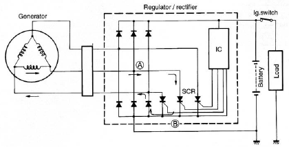
The circuit of the Suzuki GSX1300 Hayabusa charging system consists of a generator, a regulator/rectifier unit, and a battery. The alternating current (AC) generated by the generator is rectified by the rectifier to produce direct current (DC), which is...
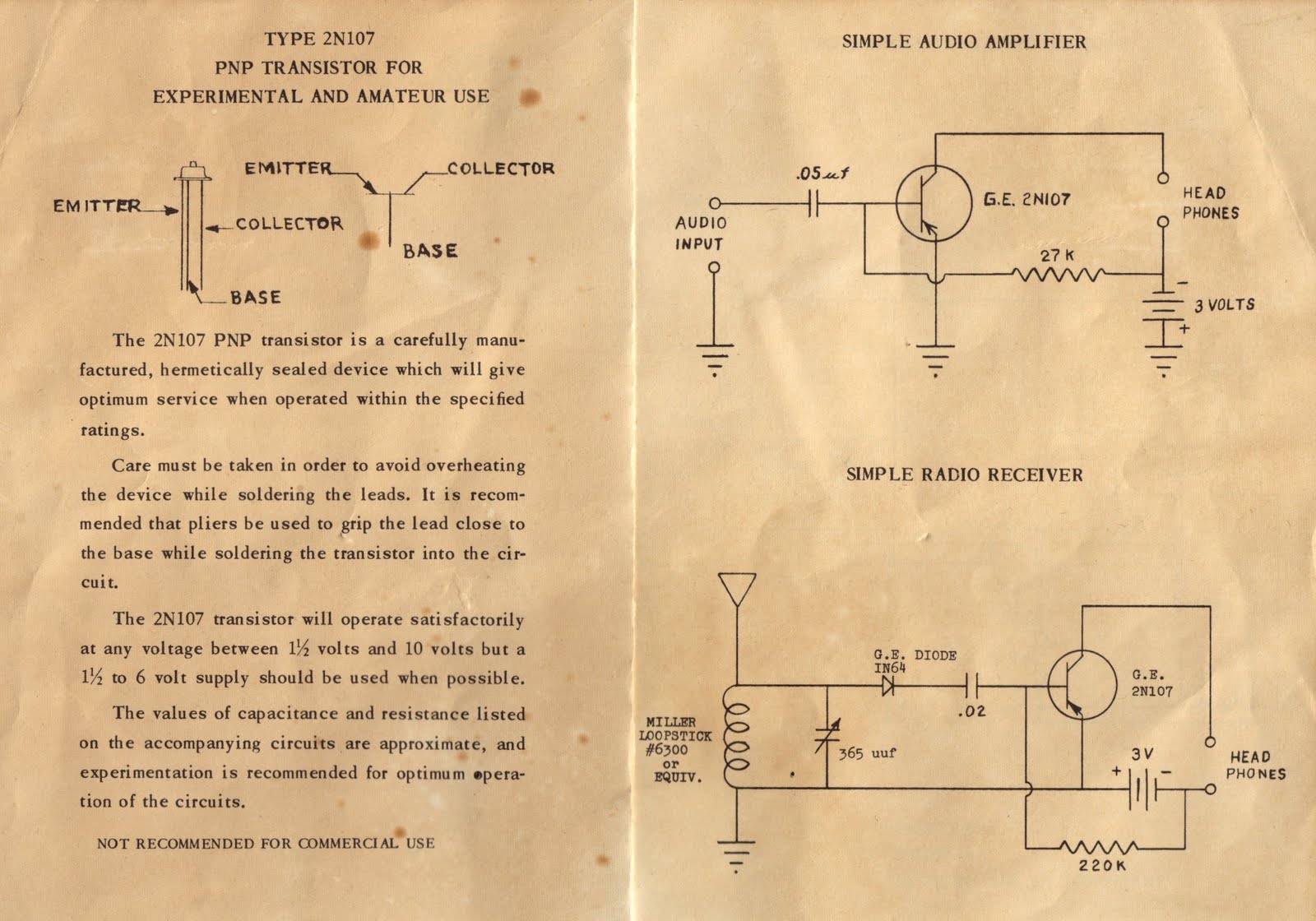
Several months ago, a surprise package arrived in the mailbox. An anonymous donor had sent three old Germanium transistors: the 2N170 and a pair of 2N107s (all date-coded December 1956), still in their original plastic tube packaging. A thin...
Grounding the blue wire at the headlamp switch causes the lights to illuminate, indicating a faulty switch. Continuity of the switch has already been verified. The relay consists of two small terminals and two larger ones. The smaller terminal,...
Warning: include(partials/cookie-banner.php): Failed to open stream: Permission denied in /var/www/html/nextgr/view-circuit.php on line 713
Warning: include(): Failed opening 'partials/cookie-banner.php' for inclusion (include_path='.:/usr/share/php') in /var/www/html/nextgr/view-circuit.php on line 713