20Mhz-vhf-crystal-oscillator

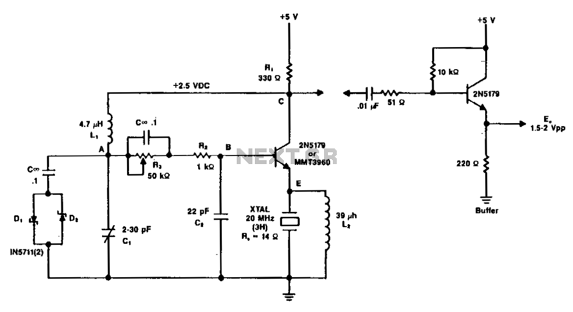
A typical circuit operating at 20 MHz is illustrated. The crystal, featuring an internal series resistance (Rs) of 14 ohms, oscillates at its third harmonic frequency. Diode clamps D1 and D2 ensure constant amplitude control. The transistor functions continuously in a linear mode throughout the entire oscillation cycle, maintaining a relatively constant load across the crystal at all times.
The circuit operates at a frequency of 20 MHz, utilizing a crystal oscillator that is specifically designed to resonate at its third harmonic. The crystal's internal series resistance of 14 ohms plays a critical role in determining the quality factor (Q) of the oscillator, influencing the stability and purity of the output frequency. This feature is essential for applications requiring precise frequency control.
In this configuration, diode clamps D1 and D2 are employed to regulate the amplitude of the oscillation. By limiting the peak voltage across the crystal, these diodes prevent distortion and ensure that the oscillation remains within the desired amplitude range. This constant amplitude control is vital for maintaining consistent performance and preventing potential damage to the crystal due to excessive voltage.
The transistor's role in this circuit is to operate in a linear mode, allowing it to amplify the oscillation signal effectively. By functioning continuously throughout the entire cycle of oscillation, the transistor provides the necessary gain to sustain the oscillation while reflecting a constant load across the crystal. This characteristic is crucial for maintaining the oscillator's stability and minimizing frequency drift.
Overall, the combination of the crystal's specific series resistance, the diode clamps for amplitude control, and the linear operation of the transistor creates a reliable and stable oscillator circuit suitable for various electronic applications. The design ensures that the circuit can deliver a consistent output frequency while maintaining the integrity of the oscillation waveform.A typical circuit at 20 MHz is shown. The crystal, which has an internal series resistance Rs of 14ohm, oscillates at its third harmonic. The diode clamp Dl and D2 provides a constant amplitude control. The transistor operates continuously in a linear mode over a complete cycle of oscillation, and reflects a reasonably constant load across the crystal at all times.