
20W Bridge Car Amplifier based TDA7240A
The bridge amplifier circuit utilizing the TDA7240A is engineered to enhance audio performance in automotive environments. This power amplifier IC is particularly adept at driving speakers in a bridge configuration, allowing for higher output power and improved efficiency compared to traditional amplifiers.
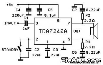
In the schematic, the TDA7240A is the central component, which requires minimal external components for operation. Typically, these components include resistors for gain setting, capacitors for filtering, and possibly inductors for additional stability in the audio signal path. The power supply section is crucial, as it must provide adequate voltage and current to meet the demands of the amplifier during peak audio signals.
The bridge configuration involves connecting two amplifiers in such a way that they drive the speaker in opposite phases. This method effectively doubles the voltage across the speaker, thereby increasing the power output without requiring a larger power supply. The output stage typically features complementary push-pull transistors that facilitate this operation, ensuring that the output signal remains linear and free of distortion.
Thermal management is also an important consideration in the design. The TDA7240A may require a heatsink to dissipate heat generated during operation, especially at higher output levels. Proper grounding and layout techniques should be employed to minimize noise and interference, ensuring high-quality audio reproduction.
Overall, the bridge amplifier circuit with the TDA7240A is a robust solution for enhancing car audio systems, delivering significant power output while maintaining simplicity in design and implementation.The following circuit diagram is a bridge amplifier which specially designed for car audio system. The circuit is very simple with few external components supporting the power IC TDA7240A. This circuit will produce a maximum power output of.. 🔗 External reference
Related Circuits
The current mode amplifier offers the advantage of higher frequency operation, and the LM359 serves as an operational amplifier of this type. The current mode amplifier is designed to operate with input signals in the form of current rather than...
Each power supply, whether linear or switching, operates in at least two modes: constant voltage (CV) and constant current (CC). The power supply can function in either mode, with the other serving as a protective mode for both the...
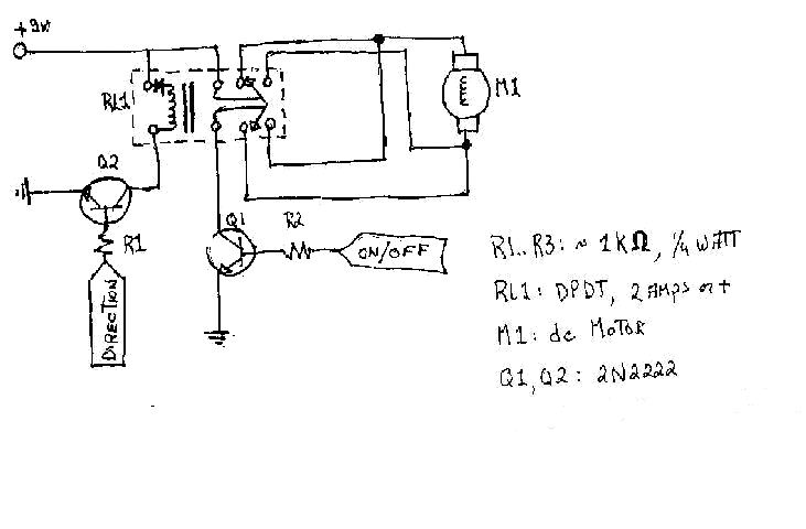
To create the circuitry described, a computer software capable of controlling a parallel port is required, with an estimated cost of approximately $30. For instance, a transistor (model number 2N2222) is priced around $0.50, while a DPDT relay costs...
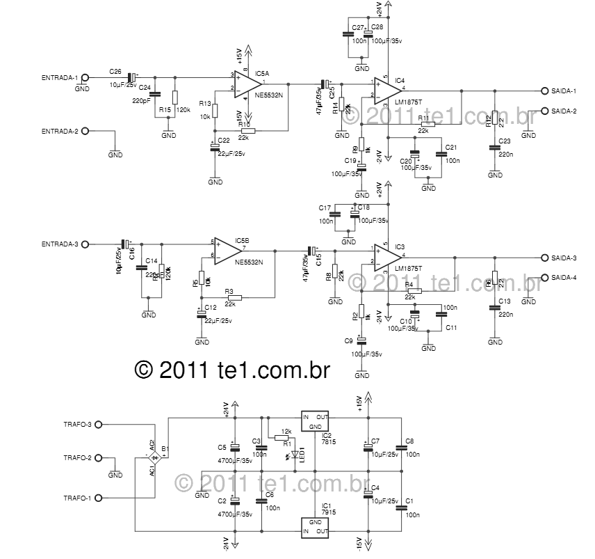
The LM1875 delivers 20 watts into a 4 or 8-ohm load on ±25V supplies. Using an 8-ohm load and ±30V supplies, over 30 watts of power may be delivered. The amplifier is designed to operate with a minimum of...
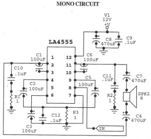
The following circuit illustrates an audio amplifier mono circuit diagram. This circuit is based on the LA4555 integrated circuit (IC). Features include a mono configuration and a power output of 2.3 watts. The audio amplifier circuit utilizing the LA4555 IC...
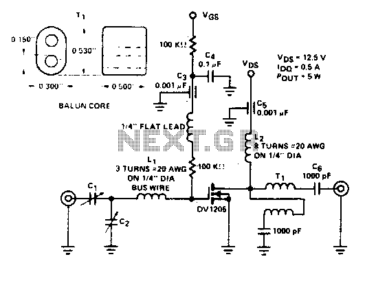
Cl. C2 ARCO #462, 2 to 60 pF, trimmer capacitors Li, 3 turns of #20 AWG wire on 1/4" diameter L2, β turns of #20 AWG on 1/4" diameter Ti. Additionally, there is 1 turn of 25 Ω coax...
Warning: include(partials/cookie-banner.php): Failed to open stream: Permission denied in /var/www/html/nextgr/view-circuit.php on line 713
Warning: include(): Failed opening 'partials/cookie-banner.php' for inclusion (include_path='.:/usr/share/php') in /var/www/html/nextgr/view-circuit.php on line 713