
20Wpp Audio Amplifier with Bass
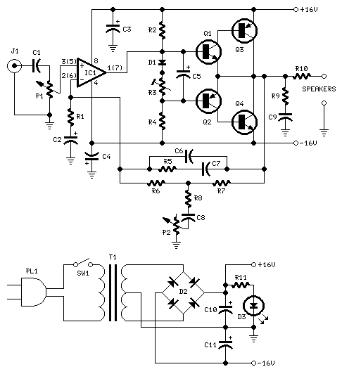
This audio amplifier circuit is designed to deliver a balanced audio output while addressing the limitations of bass response in small loudspeaker systems. The NE5532 dual IC is a robust choice for this application due to its low noise characteristics and ability to drive moderate loads effectively. The amplifier operates within a specified voltage range, which restricts the output power but ensures stability and reliability.
The inclusion of a bass-boost control in the feedback loop is a significant feature, allowing users to enhance low-frequency performance without introducing distortion. The specified frequency response curve indicates that even at lower frequencies, the amplifier maintains a degree of clarity and presence, making it suitable for a variety of audio applications, including home theater systems and portable speaker setups.
Grounding is a critical aspect of this design, as improper grounding can lead to unwanted noise and interference. The recommendation to connect the ground points of multiple components at a single location helps to maintain a common reference point, reducing the risk of ground loops. Furthermore, the connection of capacitor C9 to the output ground aids in the stabilization of the output stage, ensuring that the amplifier operates efficiently and delivers a clean audio signal.
Overall, this amplifier design presents a practical solution for users seeking a compact and effective audio amplification system, leveraging commonly available components while providing features that enhance performance and usability.This design is based on the 18 Watt Audio Amplifier, and was developed mainly to satisfy the requests of correspondents unable to locate the TLE2141C chip. It uses the widespread NE5532 Dual IC but, obviously, its power output will be comprised in the 9. 5 - 11. 5W range, as the supply rails cannot exceed ±18V. As amplifiers of this kind are freque ntly used to drive small loudspeaker cabinets, the bass frequency range is rather sacrificed. Therefore a bass-boost control was inserted in the feedback loop of the amplifier, in order to overcome this problem without quality losses. The bass lift curve can reach a maximum of +16. 4dB @ 50Hz. In any case, even when the bass control is rotated fully counterclockwise, the amplifier frequency response shows a gentle raising curve: +0.
8dB @ 400Hz, +4. 7dB @ 100Hz and +6dB @ 50Hz (referred to 1KHz). A correct grounding is very important to eliminate hum and ground loops. Connect in the same point the ground sides of J1, P1, C2, C3 &C4. Connect C9 at the output ground. 🔗 External reference
Related Circuits
When the power supply reaches the circuit and the input signal is applied, the sound signal is processed through capacitor C1 and resistor R1 for signal coupling and noise reduction. The modified signal then reaches pin 3 (non-inverting) of...
A Selective Amplifier 10dB for FM/VHF region. Note that some devices to be used SMD components and may have a minimum sales volume. Device works very well as an FM external amplifier "when used for example in car /...
My generator can produce sine- and squarewaves with frequencies between 1 Hz and 100 kHz and amplitudes ranging from zero to 1.55 Veff in 600 Ohms. Sinewave distortion is 0.1% or less between 20 Hz and 20 kHz, somewhat...
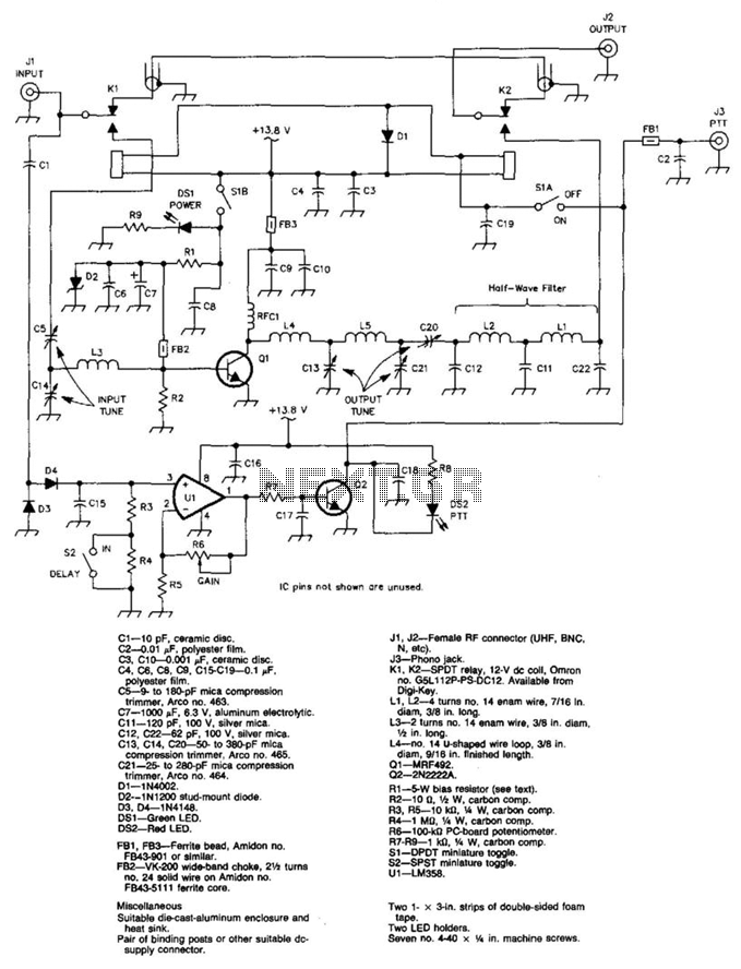
A 100 W output at 50 MHz is available from this circuit. U1 and Q2 form a T-R relay driver, switching the amplifier on when RF input at J1 is sensed. During receive periods, J1 and J2 are directly...
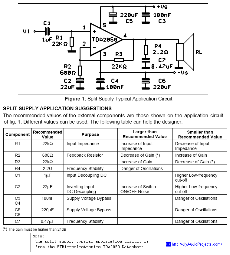
DIY TDA2050 Non-Inverting Chip Amplifier project constructed on a protoboard. The TDA2050 is a popular audio power amplifier integrated circuit designed for various audio applications. This non-inverting amplifier configuration is particularly valued for its simplicity and effectiveness in delivering high-quality...
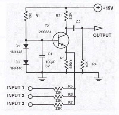
This single transistor audio mixer is utilized in an amplifier circuit design featuring a base-driven transistor, with its emitter being current-controlled. This audio mixer circuit employs a single transistor to facilitate the mixing of audio signals. The transistor operates in...