
24 Second Shot Clocks
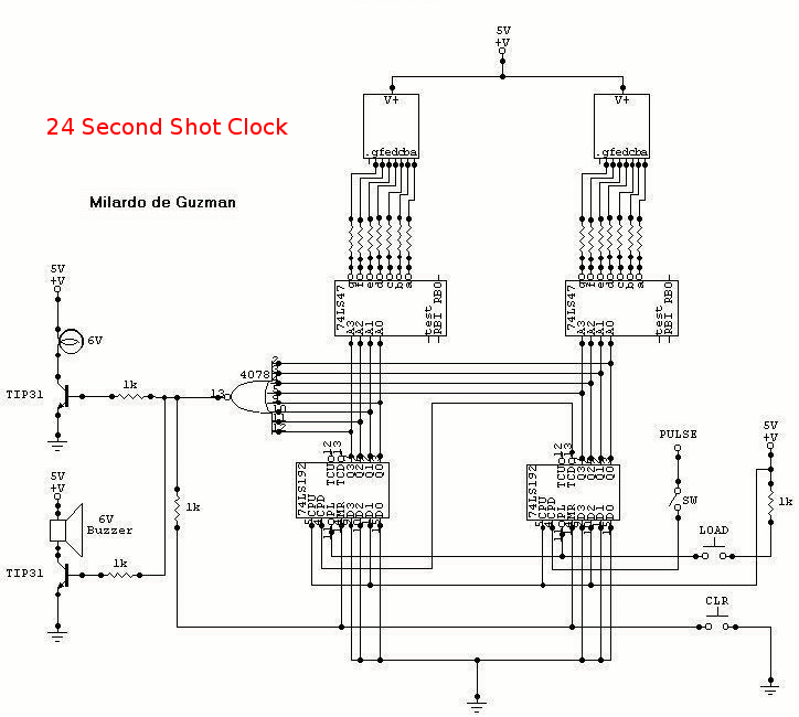
The circuit described operates as a countdown timer with additional functionalities for alerts and control. The core of the system revolves around a 555 timer configured in astable mode, generating a pulse output that serves as the clock signal for the countdown. The timer must be calibrated to ensure accurate timing corresponding to real-world seconds, which may involve adjusting resistor and capacitor values in the 555 timer circuit.
The LOAD switch and Reset switch are critical components for initializing the countdown. When pressed simultaneously, they set the counter to start from 24 seconds. If not pressed together, the counter defaults to 99, indicating a secondary operational mode or error state. The design must incorporate a mechanism to prevent erroneous counts due to unintentional switch presses.
The PAUSE switch is equipped with a debouncer circuit to eliminate any noise or bouncing that may occur when the switch is activated. This ensures that the counter maintains its state accurately during pause and resume operations. The debouncer can be implemented using a simple RC network or a dedicated debouncing IC, which provides a clean transition for the switch signal.
The NOR gate plays a pivotal role in the countdown mechanism. When the counter reaches zero, the NOR gate's output transitions to a logic high, which is used to trigger the two transistors. These transistors act as switches, controlling the power to the buzzer and light. The buzzer provides an audible alert, while the light serves as a visual indicator of the countdown completion. The transistors remain active until both the LOAD and Reset switches are pressed again, allowing for a reset of the system.
Finally, the entire circuit operates on a +5V power supply, ensuring compatibility with common digital components and maintaining low power consumption. Proper power management and decoupling capacitors should be incorporated to stabilize the power supply and prevent voltage dips during operation. Overall, this circuit design effectively combines timing, control, and notification functions in a compact and reliable manner.To start in 24 seconds; 24s LOAD SW and Reset SW should be push simultaneously. If not, the count will start in 99. Pulse input can be connected to 555 astable multivibrator but must be calibrated for real time clock. The PAUSE SW must have a Switch Debouncer so that the counter will count normal when counting is paused and then turn-on.
When the count reach 00, the NOR gate will have an output of logic1 that will turn on the two transistor. The buzzer will rung and light will turn on. The two transistors are continuously turn-on not until LOAD SW and Reset SW is push. All have a +5v power supply. 🔗 External reference
Related Circuits
A band-stop filter (BSF) utilizing an integrated operational amplifier is designed to suppress signals within a specific frequency band, allowing signals outside this band to pass with minimal attenuation. This configuration is achieved through a two-stage network, which employs...
The reciprocating detector was designed by R. S. Badessa at MIT. The RD features a carrier-synthesized reference signal and requires no external beat frequency oscillator (BFO). The circuit offers advantages over conventional detectors by automatically adjusting its BFO level...

This filter circuit, which utilizes the LM1458 or a similar operational amplifier, has a frequency response ranging from 300 Hz to 3.4 kHz, exhibiting a roll-off of 12 dB per octave outside the passband. Section A serves as the...
Electronics tutorial about the monostable multivibrator circuit, also known as a one-shot monostable multivibrator, used as a pulse generator circuit. The monostable multivibrator is a crucial component in electronic circuits, functioning as a pulse generator that produces a single output...
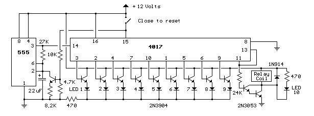
This circuit provides a visual 9-second delay using 10 LEDs before closing a 12-volt relay. When the switch is closed, the 4017 decade counter will reset to zero, illuminating the LED connected to pin 3. The output at pin...
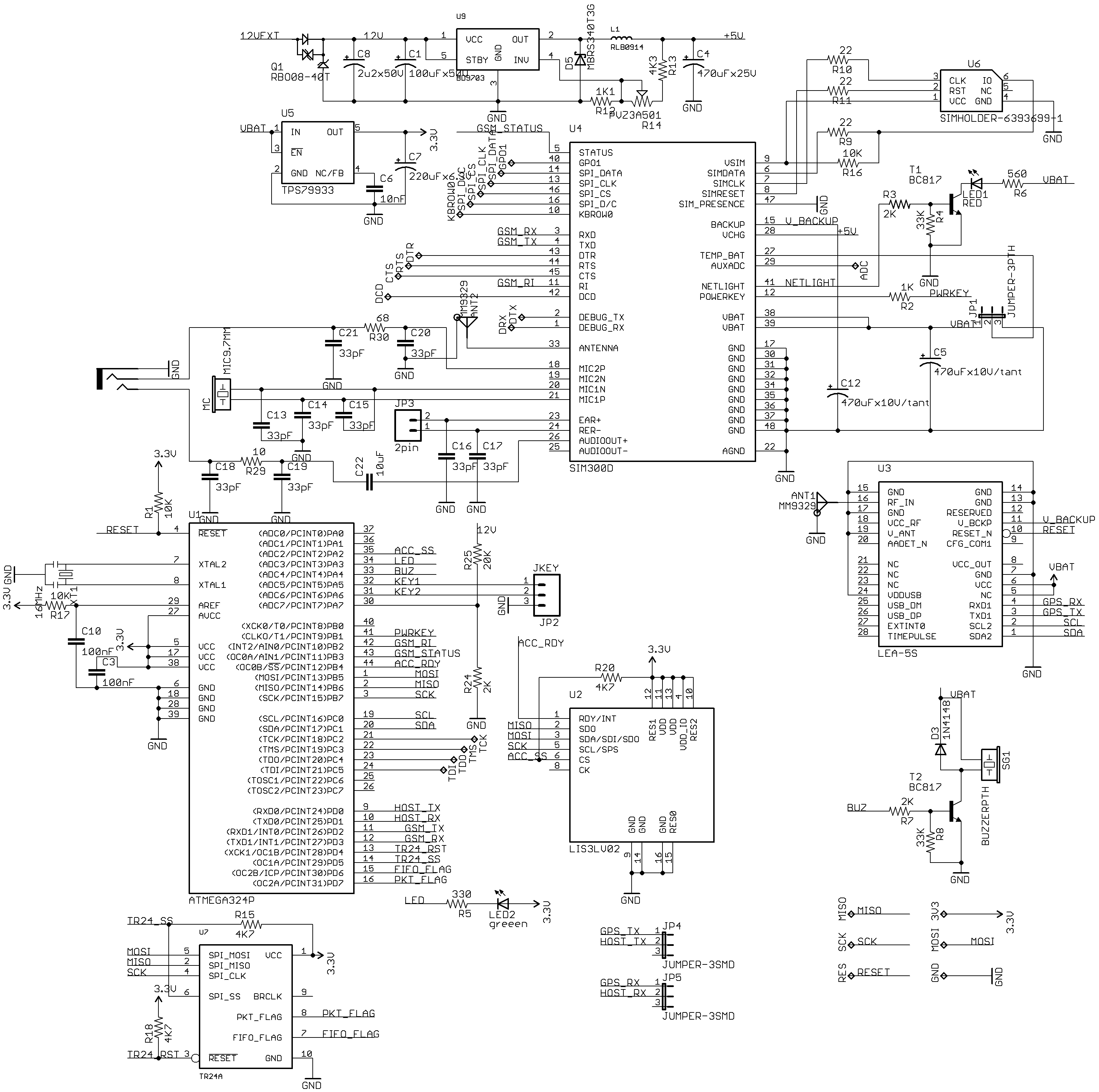
New uTracker on GE865 with a compact design. This updated version of the tracker features the SIM300DZ and EB-230/LEA-5S modules. It includes an OBD-II (ISO) sensor, an accelerometer, and an RFID reader. Additionally, a TR24 2.4GHz module is incorporated,...
Warning: include(partials/cookie-banner.php): Failed to open stream: Permission denied in /var/www/html/nextgr/view-circuit.php on line 713
Warning: include(): Failed opening 'partials/cookie-banner.php' for inclusion (include_path='.:/usr/share/php') in /var/www/html/nextgr/view-circuit.php on line 713