
24v 7ah lead acid battery charger
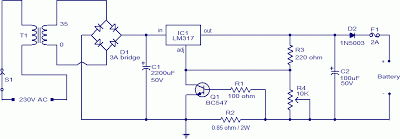
The lead-acid battery charger circuit is structured to efficiently charge two 12V lead-acid batteries connected in series, effectively creating a 24V charging system. The use of the LM317 voltage regulator allows for adjustable output voltage and current, which is crucial for optimizing the charging process and prolonging battery life. The design incorporates a current-limiting feature through resistor R2, which is critical for preventing overcurrent conditions that could damage the batteries.
The transformer T1 is selected based on the required input voltage and output current specifications, ensuring that it can adequately handle the mains voltage while providing the necessary reduced voltage for charging. The bridge rectifier D1 converts the AC voltage from the transformer into DC voltage, which is essential for charging lead-acid batteries. The filtering action of capacitor C1 smooths out any ripple in the rectified output, providing a more stable voltage to the batteries.
The inclusion of diode D1 is an essential safety feature, protecting the circuit from potential damage due to reverse current flow when the charger is not in operation. This prevents the batteries from discharging back through the charger, which could lead to reduced battery performance or failure.
The adjustable voltage output, controlled via potentiometer R4, allows the user to set the charging voltage to 28V, which is appropriate for charging two 12V batteries in series. This flexibility is particularly beneficial for various battery conditions and states of charge. The circuit design emphasizes user safety and battery health, making it suitable for home or workshop applications where lead-acid batteries are commonly used.This lead acid battery charger circuit is designed in response to a request from Mr. Devdas. C. His requirement was a circuit to charge two 12V/7AH lead acid batteries in series. Anyway he did not mentioned the no of cells per each 12V battery. The no of cells/battery is also an important parameter and here I designed the circuit assuming each 12V b attery containing 6 cells. When two batteries are connected in series, the voltage will add up and the current capacity remains same. So two 12V/7AH batteries connected in series can be considered as a 24V/7AH battery. The circuit given here is a current limited lead acid battery charger built around the famous variable voltage regulator IC LM 317.
The charging current depends on the value of resistor R2 and here it is set to be 700mA. Resistor R3 and POT R4 determines the charging voltage. Transformer T1 steps down the mains voltage and bridge D1 does the job of rectification. C1 is the filter capacitor. Diode D1 prevents the reverse flow of current from the battery when charger is switched OFF or when mains power is not available. To setup the charging voltage, power ON the charger and hook up a voltmeter across the output terminals and adjust R4 to make the voltmeter read 28V.
Now the charger is ready and you can connect the batteries. 🔗 External reference
Related Circuits
Heavy-duty portable charger for USB devices (phones, iPad, etc.). Have you ever needed to charge your phone on the go? Unable to find a wall socket to charge your iPod?.. The heavy-duty portable charger is designed to provide a reliable...
The charging apparatus depicted in the schematic circuit has a maximum output current of 20A and a maximum charging voltage of 80V. It can be adjusted starting from 0V, making it suitable for charging various types of batteries. The...
Charge current: I=0.45V/R2 Power-dissipation by R2: (0.45 * 0.45 / R2) Please adjust 13.8V by R5 without connected battery. More: D1 - D4, D6: charge-current less than 1A: 1N4001 (up to 1N4007) charge-current up to 2A: 1N5401 D5: 1N4184,...
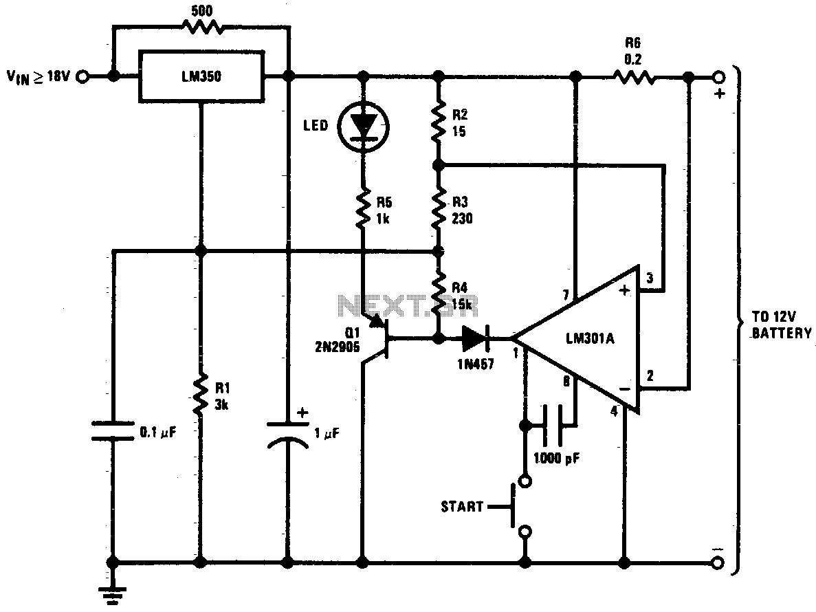
This circuit is a high-performance charger for gelled electrolyte lead-acid batteries. The charger quickly recharges the battery and automatically shuts off when it reaches full charge. Initially, the charging current is limited to 2A. As the battery voltage rises,...
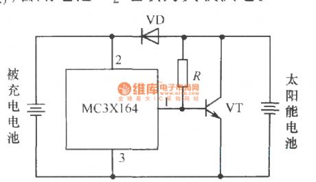
The following circuit illustrates a current-limited solar battery charger circuit diagram. This lead-acid or Ni-Cd battery charger circuit diagram utilizes solar energy to charge a 6-volt, 4.5 Ah rechargeable battery for various applications. It represents a straightforward solar battery...
Using this circuit will give good charging results to a sealed lead acid battery, like I use in the metal detector. This circuit is extremely small in size and has a low parts count, making it ideal in some...
Warning: include(partials/cookie-banner.php): Failed to open stream: Permission denied in /var/www/html/nextgr/view-circuit.php on line 713
Warning: include(): Failed opening 'partials/cookie-banner.php' for inclusion (include_path='.:/usr/share/php') in /var/www/html/nextgr/view-circuit.php on line 713