
3.6 Volt cell phone battery meter circuit
The circuit employs a TL431 voltage reference to create a stable reference point for the LED indicators. The TL431 is a programmable shunt voltage reference that can be adjusted to provide a desired output voltage, in this case, set to 3.9 volts. This voltage level is crucial for accurately representing the battery voltage on the LED bar graph.
The 1K resistor connected to the TL431 serves to limit the current flowing through the reference pin and helps in establishing the desired output voltage. The 5K adjustable resistor allows for fine-tuning of the lower threshold voltage at pin 14, which controls the activation of the LED indicators. By adjusting this resistor, the user can set the point at which the first LED lights up, indicating that the battery voltage has reached a specific lower limit.
The 4 LED bar graph visually represents the battery voltage level, with each LED corresponding to a specific voltage range. When the battery voltage is above the set threshold, the corresponding LEDs will illuminate, providing an immediate visual indication of the battery status. This circuit is particularly useful in portable electronic devices, where monitoring battery levels is essential for ensuring optimal performance and preventing unexpected shutdowns.
Overall, the design is straightforward yet effective, utilizing common electronic components to achieve a functional and user-friendly battery voltage monitoring solution.This is a similar circuit to the above and provides a 4 LED bar graph indicating the voltage of a common 3.6 volt Lithium - Ion recharable cell phone battery. The reference voltage is provided by a TL431 programmable voltage source which is set to 3.9 volts where the TL431 connects to the 1K resistor.
The lower reference for the LED at pin 14 is set with the 5K adjustable resistor.. 🔗 External reference
Related Circuits
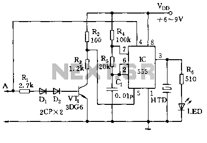
This circuit is designed for children's entertainment and can be installed on bicycles, battery-powered cars, motorcycles, as well as models and various games and toys. When switch SW1 is positioned as indicated in the circuit diagram, it generates the...
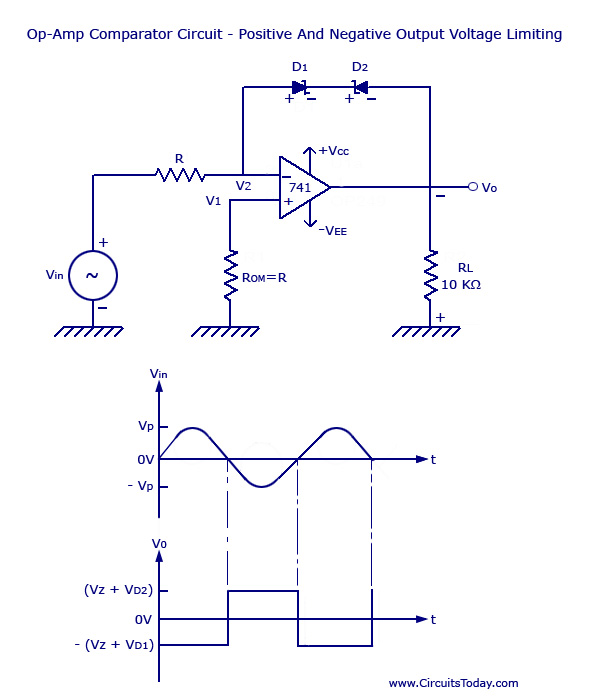
Voltage Limiter Circuit Using Op-amp - Circuit Diagram, Waveform, Positive and Negative Voltage Limiters. The voltage limiter circuit utilizing an operational amplifier (op-amp) serves to restrict the output voltage to predefined levels, effectively preventing it from exceeding or falling below...
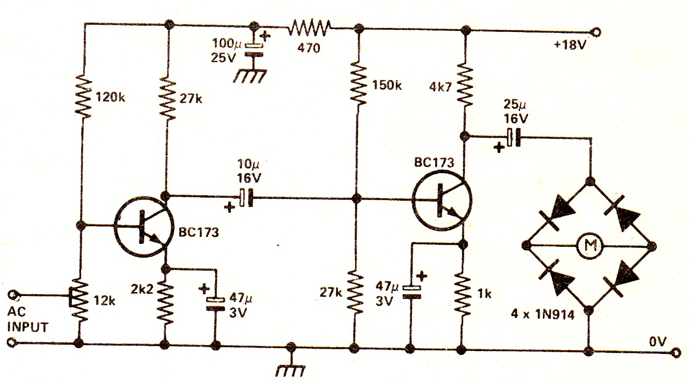
The circuit illustrates a two-stage voltage amplifier that drives a recording level meter. An AC signal input is amplified and rectified, with the resulting DC voltage displayed on the meter. This circuit is compatible with tape recorders or audio...

TDA7262 stereo 20 watts audio amplifier circuit design electronic project The TDA7262 is an integrated circuit designed for stereo audio amplification, capable of delivering up to 20 watts per channel. This amplifier circuit is suitable for various applications, including home...
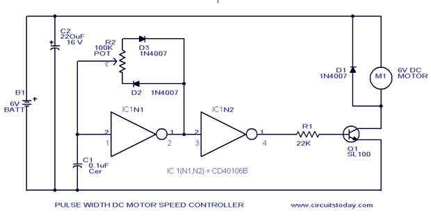
A simple PWM motor speed control circuit with a diagram and schematic for low power DC motors. This easy-to-make PWM DC motor controller is created using the IC CD40106B. The PWM (Pulse Width Modulation) motor speed control circuit utilizes the...
The circuit utilizes a 555 timer along with resistors R4, R5, and capacitor C1 configured in a controllable multivibrator mode. This setup forces the reset terminal (pin 4) to a specific state, allowing for control of the external logic...
Warning: include(partials/cookie-banner.php): Failed to open stream: Permission denied in /var/www/html/nextgr/view-circuit.php on line 713
Warning: include(): Failed opening 'partials/cookie-banner.php' for inclusion (include_path='.:/usr/share/php') in /var/www/html/nextgr/view-circuit.php on line 713