
3 channel audio splitter
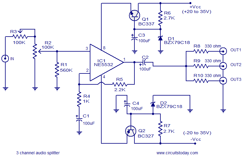
The circuit utilizes the NE5532 operational amplifier, known for its low noise characteristics and high fidelity, which is crucial for audio applications. The configuration as a non-inverting amplifier with a gain of 3 means that the output voltage will be three times the input voltage, providing adequate amplification for the audio signal before it is split into three channels. The use of potentiometers R2 and R3 allows for adjustable input levels, enabling fine-tuning of the audio signal before amplification.
Capacitor C2 plays a critical role in blocking any DC offset present in the audio signal, ensuring that only the AC components are amplified and sent to the output channels. The output is then divided among three separate paths through resistors R8, R9, and R10, which can be used to drive different audio devices or channels, maintaining signal integrity across all outputs.
The voltage regulation section of the circuit is essential for providing stable power to the NE5532, ensuring optimal performance. The positive voltage regulator formed by Q1, C3, R6, and D1 supplies the necessary positive voltage, while the negative voltage regulator created by Q2, C4, R7, and D2 provides the negative voltage required for the dual-supply operation of the op-amp. This dual supply configuration enhances the dynamic range and overall audio quality of the circuit.
For applications where a dual power supply is not available, the voltage regulator sections can be utilized to generate the required voltages from a single supply, ensuring versatility in various setups. This circuit design is suitable for a range of audio applications, including mixing consoles, audio interfaces, and other professional audio equipment where high-quality sound reproduction is essential.Here is the circuit diagram of a simple 3 channel audio splitter based on the IC NE5532. NE5532 is a dual internally compensated low noise opamp from Fairchild semiconductors. It has a high small signal and power bandwidth, making it well suitable for high quality audio applications. Here the IC1 is wired as a non inverting amplifier with a gain 3 . The audio signal to be splited is applied to the non inverting pin of IC1 through the POTs R2 and R3. Capacitor C2 works as a DC decoupler and resistors R8, R9, R10 splits the output of the IC1 into three channels.
Components Q1, C3, R6, D1 forms a positive voltage regulator while components Q2, C4, R7, D2 forms a negative voltage regulator. If you have a +12/-12 V dual power supply, then the circuit can be directly powered from it and the regulator sections can be avoided.
🔗 External reference
Related Circuits
Most sound cards in computers lack stereo input for microphones, but they do have stereo inputs for high-level signals (Line). This circuit utilizes the Line input of the sound card to connect two mono microphones to the sound card's...
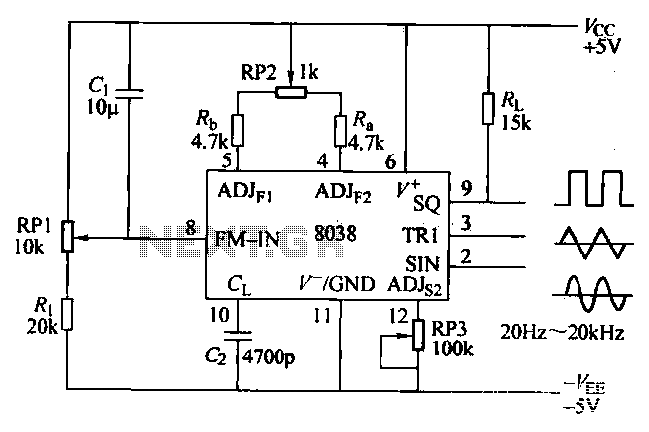
The ICL8038 function generator is an audio composition device that utilizes the ICL8038 integrated circuit. The resistance Ri potentiometer RP1 is used to determine the flow potential. Typically, the output is set to approximately 2Vcc / 3. Lowering the...
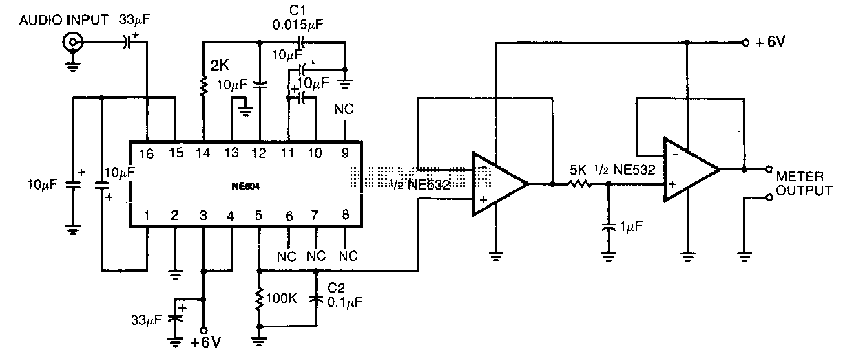
This circuit consumes very little power, drawing less than 5 mA from a single 6-V power supply, making it suitable for portable battery-operated devices. Its compact size and low power consumption do not compromise its performance, offering a dynamic...
In the drawing, a simple but powerful power amplifier is presented. Its difference from classic designs, which use differential amplifiers in their input, is that this amplifier uses a complete NE5534 at its input. Thus, it is necessary to...
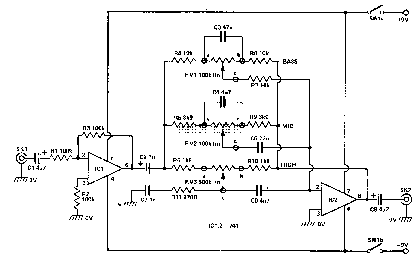
The input signal is fed through SKI to the first active stage, which is constructed around IC1. This stage is configured as a non-inverting amplifier, with its gain determined by the ratio of R3 and R1. In this configuration,...
This miniature audio amplifier provides an output of up to 250mW and can function as a final stage audio amplifier for radio sets. The schematic is straightforward, featuring one BC transistor. The described miniature audio amplifier is designed for efficient...
Warning: include(partials/cookie-banner.php): Failed to open stream: Permission denied in /var/www/html/nextgr/view-circuit.php on line 713
Warning: include(): Failed opening 'partials/cookie-banner.php' for inclusion (include_path='.:/usr/share/php') in /var/www/html/nextgr/view-circuit.php on line 713