
3 digits Digital volt meter
The digital voltmeter circuit employs the PIC16F676 microcontroller, which is central to its operation. The microcontroller's ADC allows for the conversion of the analog voltage signal into a digital format suitable for display. The circuit design includes a voltage divider composed of resistors R1 and R2 to scale down the input voltage to a range compatible with the ADC. This is critical for ensuring that the voltage does not exceed the ADC's maximum input level.
The variable resistor VR1 serves as a calibration tool, enabling the user to fine-tune the maximum voltage that the display can represent. By adjusting VR1, the output from the voltage divider can be set to match the desired full-scale reading on the 7-segment display, enhancing measurement accuracy.
The choice of using the AN3 (RA4) pin for analog input is significant, as it is one of the designated ADC channels in the PIC16F676 microcontroller. This configuration allows for efficient use of the available channels, leaving the remaining pins free for digital input/output operations. The circuit's simplicity facilitates easy integration into various applications, such as battery monitoring or power supply testing, where voltage measurement is essential.
In summary, this digital voltmeter circuit is an effective implementation of a microcontroller-based measurement system, utilizing the capabilities of the PIC16F676 to achieve accurate voltage readings displayed on a 7-segment display. The design considerations, including the voltage divider and calibration adjustments, contribute to its functionality and versatility in practical applications.This is simple 3-digits digital volt meter. PIC16F676 used to read analog signal(voltage) and display the value on 3-digits 7-segment. You can apply to mesasure DC currant with parallel Rshunt but I`m not descript here. As we know the most of PIC microcontroller has 8-bit/10-bit on-chip Analog to Digital converter module. In this project I use PIC16 F676 which have ADC 10-bits 8 channel but this project use only one channel for measure voltage input for other pin set as digital I/O. From the schematic above the input voltage divided by R1 and R2 (voltage divider). VR1 parallel with R2 use to adjust appropriate display full scale voltage. The divided input voltage will connected to AN3(RA4) which set as analog input. 🔗 External reference
Related Circuits
Software on a MacBook Pro includes Laidman & Katsura's WaveWindow, which functions as a software oscilloscope. It is beneficial for individuals working with sound on the Mac, offering an educational and entertaining experience. Additionally, Faberacoustical's Signal Scope allows for...

The following circuit is a PC thermometer utilizing the DS1621. Features include the ability to plug into any available PC COM port, a temperature range of -20 to 125°C, and the capability to display temperatures in both Celsius (°C)...
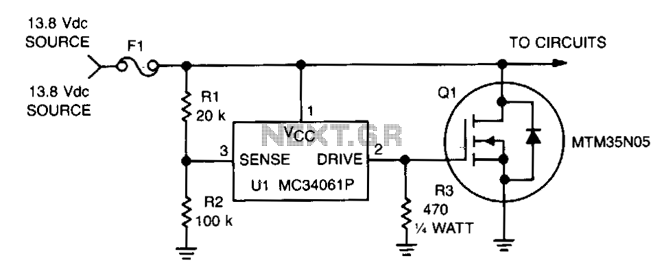
This circuit protects expensive portable equipment against all types of improper hookups and environmental hazards that could cause an overvoltage condition. It operates very quickly and does not latch up; rather, it recovers when the overvoltage condition is removed....

This device is designed to be a simple, inexpensive comparator intended for use in a solar cell power supply setup where a quick "too low" or "just right" voltage indicator is needed. The circuit consists of one 5V regulator,...
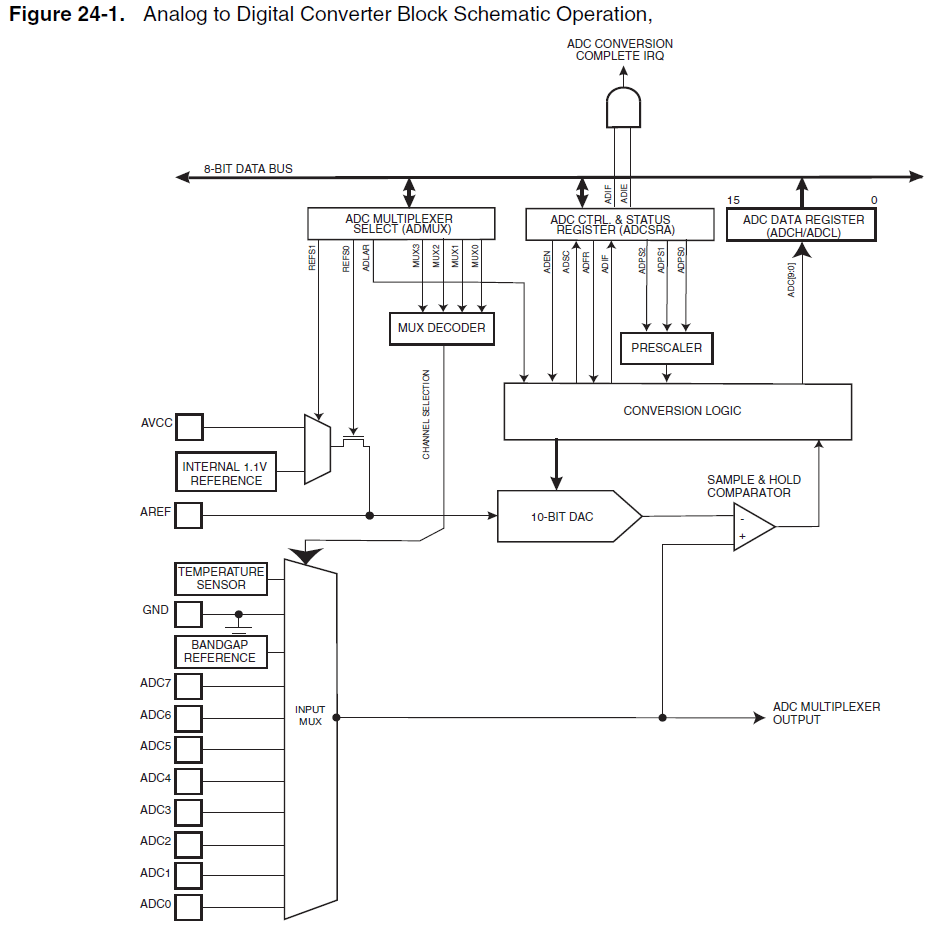
When using the internal 1.1V reference for the ADC, if the analog input exceeds 1.1V, such as 2.5V, it will not harm the microcontroller. Instead, the ADC value will clip at 0x3FF. Based on practical experience, it has been...
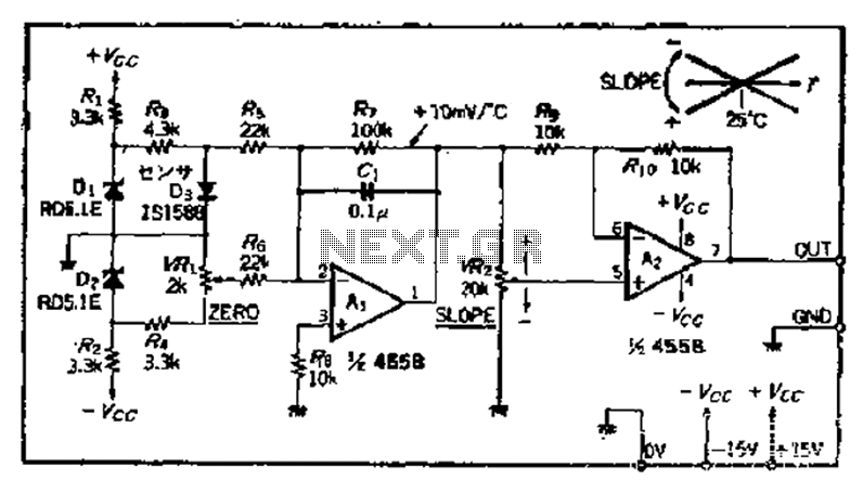
A temperature sensor can be created using a standard silicon diode, which produces approximately 2.2 mV per degree Celsius variation. An operational amplifier (OP amplifier) is utilized with a positive reference temperature (room temperature). The output signal is amplified...
Warning: include(partials/cookie-banner.php): Failed to open stream: Permission denied in /var/www/html/nextgr/view-circuit.php on line 713
Warning: include(): Failed opening 'partials/cookie-banner.php' for inclusion (include_path='.:/usr/share/php') in /var/www/html/nextgr/view-circuit.php on line 713