
30 watt power fm transmitter with 2sc1946a circuits

The power amplifier circuit for the 30-watt FM transmitter is designed to enhance the signal strength of the RF output generated by the driver stage. The choice of the 2SC1946A transistor is significant due to its high current handling capacity and frequency response, making it suitable for FM transmission applications. The 13.8-volt DC power supply is standard for many RF applications, providing the necessary voltage level for optimal performance.
The circuit layout should ensure that the connections are short and direct to minimize parasitic inductance and capacitance, which could affect the performance at high frequencies. The output stage must be thermally managed, as power transistors can generate significant heat during operation. Adequate heat sinking or cooling mechanisms should be implemented to maintain the reliability of the circuit.
The impedance matching using trimmer capacitors is critical for maximizing power transfer. The adjustment process involves tuning the capacitors while monitoring the output power and signal integrity. This ensures that the driver stage's output is effectively coupled to the power amplifier without reflections that could lead to signal degradation.
Furthermore, the inclusion of a high-pass filter at the output stage serves a dual purpose: it eliminates unwanted low-frequency signals and harmonics, thereby improving the quality of the transmitted signal and protecting the subsequent stages from potential damage caused by these frequencies. The filter design should be carefully calculated to ensure it operates effectively within the desired frequency range of the FM transmission.
In conclusion, the successful implementation of this 30-watt FM transmitter power amplifier circuit hinges on careful selection of components, precise tuning of the circuit parameters, and effective thermal management, ensuring a robust and efficient transmission system.The following circuits is one of the power amplifier circuit for FM transmitter with an output power of 30 watts. Power amplifier circuits for 30-watt FM transmitter, the transmitter uses power transistor type 2SC1946A.
Power FM transmitter circuits uses a 13. 8 volt DC voltage source. Power supply for power amplifier circuit can be drawn from the battery (accumulator) or from a power supply. Impedance output circuit 30 watt FM transmitter power is 50 Ohm, as well as the transmitter input impedance of 50 Ohm line. Complete circuits along with a list of components to make a 30 watt FM transmitter power can be seen in the figure below.
Power circuits 30 watt FM transmitter as shown in the picture above has the path to the input impedance of 50 Ohm. This input path is the path to the input RF signal from an FM transmitter driver circuits is used prior to FM transmitter power is 30 watts.
Driver circuits for an FM transmitter with 30 watts of transmitter power 2SC1946A transistors, the driver can use the FM transmitter with a transmitter power transistor 2sc1972 or 2sc1970. Trimer capacitors C5 and C12 in the circuit power FM transmitter to function as an adjustment on the impedance between the output driver circuit FM transmitter, the input circuits power FM transmitter above.
Then trimer capacitors 11 and C13 serve for adjusting the impedance of circuits tansmitter power FM transmitter with an antenna that is used. In the above transmitter output power circuits equipped with a high pass filter be nested and aims to prevent leakage of the transmit power on the transmitter power circuits above.
The process of setting trimer capacitors on the input line and output circuits 30 watt FM transmitter power above shall be conducted, so that all the power of the transmitter driver can be absorbed completely by the power transmitter and the power emitted from the power above 30 watts FM transmitter can be completely absorbed by ontena so there is no leakage of RF signals in the circuit and antenna cables. 🔗 External reference
Related Circuits
The circuit of AM transmitter is designed to transmit (amplitude modulated) DSB (double side band) signals. A modulated AM signal consists of a carrier and two symmetrically spaced side bands. The two side bands have the same amplitude and...
The circuit of the transmitter is shown in Figure 1, and as you can see it is quite simple. The first stage is the oscillator, and is tuned with the variable capacitor. Select an unused frequency, and carefully adjust...
A 24V DC power supply circuit utilizing the LM7824 integrated circuit (IC). The LM7824 is a fixed output voltage regulator IC that provides 24V at a maximum current of 1.5A and is available in a TO-220 package. It is...
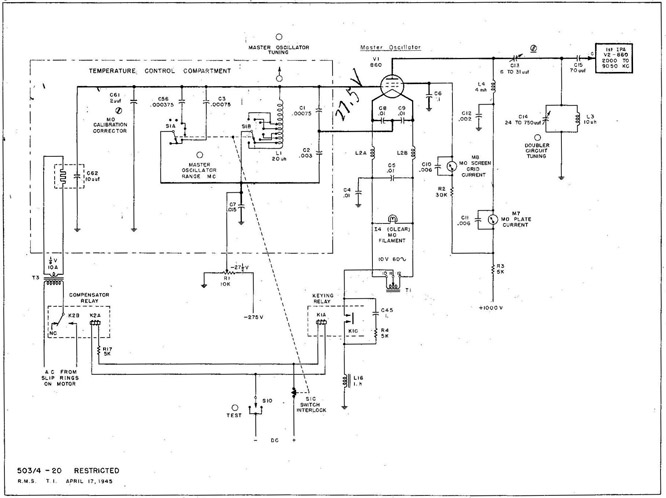
With the equipment ready for operation, the main line switch (S-831), the emergency switch (S-12), and the main line contactor contacts (K-831B) are all closed. The keying relay main contacts (K-1C) ground the center tap of the MO filament...
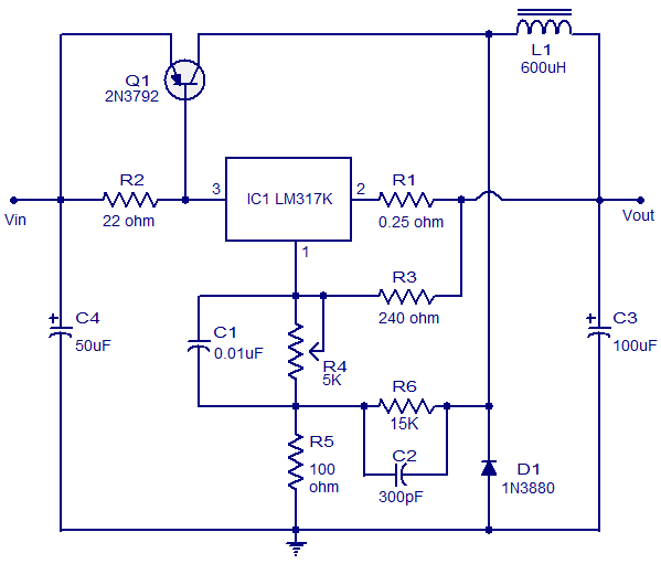
This circuit illustrates a 3A Switching Regulator Circuit based on the LM317K integrated circuit. It is designed to be simple and cost-effective. The 3A Switching Regulator Circuit utilizing the LM317K IC serves as a versatile voltage regulation solution, capable of...
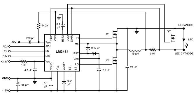
The LM3434 adaptive constant on-time DC/DC buck (step-down) constant current controller can be used to design a simple high-power LED driver application. The LM3434 provides a constant current for illuminating high-power LEDs. The output configuration allows the anodes of...
Warning: include(partials/cookie-banner.php): Failed to open stream: Permission denied in /var/www/html/nextgr/view-circuit.php on line 713
Warning: include(): Failed opening 'partials/cookie-banner.php' for inclusion (include_path='.:/usr/share/php') in /var/www/html/nextgr/view-circuit.php on line 713