
35W switching power supply circuit having a set-top box output of 5

The 35W switching power supply circuit is a versatile power management solution, particularly tailored for consumer electronic devices such as set-top boxes and multimedia equipment. The circuit's design incorporates a switching regulator topology, which enhances efficiency by minimizing power loss during voltage regulation. The five output voltages allow for a range of device compatibility, ensuring that the power supply can cater to different operational requirements.
The main outputs, +5V and +3.3V, are critical for powering digital circuits in devices like set-top boxes and VCRs, where stable voltage levels are essential for reliable operation. The additional outputs provide flexibility for other components that may require different voltage levels, thereby reducing the need for multiple power supplies in a single device.
The power supply's ability to function across a wide input voltage range (85V to 265V) makes it suitable for global applications, accommodating variations in mains voltage. This feature is particularly beneficial for devices intended for international markets, ensuring consistent performance regardless of the local power grid conditions.
Efficiency is a significant consideration in the design of this power supply, with an efficiency rating exceeding 77%. This not only reduces energy consumption but also minimizes heat generation, which is critical for maintaining the longevity and reliability of electronic components. The inclusion of under-voltage and over-voltage protection mechanisms enhances the safety of the circuit, safeguarding both the power supply and the devices it powers from potential damage due to voltage fluctuations.
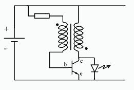
Overall, the 35W switching power supply circuit represents a well-engineered solution for powering a variety of electronic devices, combining efficiency, versatility, and safety features in a compact design.35W switching power supply circuit having a set-top box output is shown in Figure 5. The five-way voltage respectively: Uo1 (+ 30V, 100mA), Uo2 (+ 18V, 550mA), Uo3 (+ 5V, 2.5A) , Uo4 (+ 3.3V, 3A), Uo5 (-5V, 100mA). Wherein, + 5V and + 3.3V as the main output, the rest are supplemented by output from various quarters. When the AC input voltage u 220 (1 15%) V, the switching power supply total output power of 38.5W, the use of a wide range of input voltage (u 85 ~ 265V), the total output power is reduced 25W.
Can be used as set-top boxes (Set Top Box), video recorder (VCR), camcorder (CVCR) and DVD player in the switching power supply. The set-top boxes switching power supply efficiency above 77%, with under-voltage and over-voltage protection.
Related Circuits

This small FM transmitter can be modified to replace the microphone with an audio jack, allowing it to connect to an MP3 player for audio playback through car audio systems. The design is straightforward and intended for a short...
There is a requirement for a compact flashlight to illuminate small text on integrated circuits (ICs) and provide better visibility when examining disassembled components. The flashlight should have a long battery life while avoiding excessive battery consumption, such as...

ECL integrated circuit non-saturated digital logic circuits. CMOS and ECL interface circuit shown in cross. ECL (Emitter Coupled Logic) integrated circuits are designed to operate in a non-saturated mode, providing high-speed digital logic functionality. These circuits are characterized by their...

The DC panel battery is commonly utilized in power plants and substations within DC systems. To enhance the safety and reliability of the current system, an uninterrupted power supply switching circuit may be implemented. This circuit includes components such...

The schematic diagram below illustrates a high voltage generator circuit. This circuit employs a 4049 hex inverter configured as an oscillator, and it can utilize an ignition transformer from an automotive engine. A fly-back transformer may also be suitable....
This is a remote tester circuit designed to test TV and other remote controls. The circuit is simple and utilizes only a few components. The infrared sensor used in the circuit is the TSOP1738. When the infrared waves are...