
3v fm transmitter for short distance
The Colpitts oscillator is a type of electronic oscillator that utilizes a combination of capacitors and an inductor to produce oscillations at a specific frequency. In this circuit, the capacitors C3, C4, C5, and C6, along with the inductor L1, are critical components that set the resonant frequency of the oscillator. The BF982 transistor, known for its low noise and high-frequency characteristics, works in conjunction with the dual-gate MOSFET to ensure stable oscillation. The high input impedance of the MOSFET gates allows the LC tank circuit to operate without significant loading effects, maintaining the integrity of the oscillation.
The introduction of the driver stages serves a dual purpose: it enhances signal strength and provides isolation between the oscillator and the antenna. The first driver stage, implemented with the BF199 transistor, amplifies the oscillator's output while acting as a constant load, ensuring that the oscillator operates within its optimal parameters. The second driver stage, utilizing the BFR90 transistor, further boosts the signal before transmission through the antenna, ensuring adequate strength for effective radiation.
The choice of a short copper wire as an antenna is suitable for this circuit, given the low output power. The design does not necessitate a larger antenna, which could introduce additional loading and potentially affect the performance of the oscillator. This configuration leverages the compact and efficient design of the Colpitts oscillator while ensuring reliable signal amplification and transmission. Overall, this circuit design exemplifies effective use of components to achieve desired electronic oscillation and signal amplification.The important part of the circuit is formed of the Colpitts type oscillator. C3, C4, C5, C6, CD1-CD2 and L1 determines the frequency. BF982 and dual gate MOSFET are active parts in the oscillator. When the input impedance of the MOSFET gate inputs are high, LC tank is not affected. However transistors force the LC tank and cause phase shift. Two drive r stages are added to isolate the antenna from oscillator. First stage (BF199) amplifies the low signal of the oscillator and works as a constant load. The second stage (BFR90) amplifies the signal going through the antenna some more. A short copper wire can be used as an antenna here. Attaching a large antenna to this circuit is unnecessary because the output power is low. The important part of the circuit is formed of the Colpitts type oscillator. C3, C4, C5, C6, CD1-CD2 and L1 determines the frequency. BF982 and dual gate MOSFET are active parts in the oscillator. When the input impedance of the MOSFET gate inputs are high, LC tank is not affected. However transistors force the LC tank and cause phase shift. Two driver stages are added to isolate the antenna from oscillator. First stage (BF199) amplifies the low signal of the oscillator and works as a constant load. The second stage (BFR90) amplifies the signal going through the antenna some more. A short copper wire can be used as an antenna here. Attaching a large antenna to this circuit is unnecessary because the output power is low. 🔗 External reference
Related Circuits
A regenerative radio receiver is unsurpassed in comparable simplicity, weak signal reception, inherent noise-limiting and agc action and, freedom from overloading and spurious responses. The regenerative radio receiver or, even super-regenerative radio receiver or, "regen" if you prefer, are...
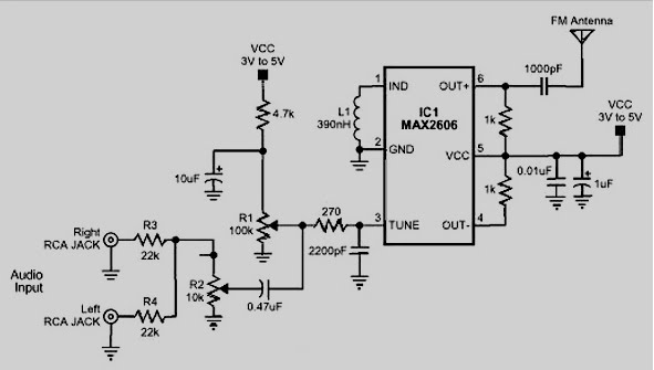
The MAX2605 and MAX2609 are compact, high-performance intermediate frequency (IF) voltage-controlled oscillators (VCOs) specifically designed for demanding portable wireless communication systems. They feature a monolithic construction with low noise and low operating power consumption, housed in a small 6-pin...
This simple transmitter operates from a 9V battery as shown above. It was built to address the challenges faced by a singing group using FM microphones in a church setting. The choir performs in an a cappella style, and...
This oscillator is known as the Colpitts oscillator and is voltage-controlled to facilitate frequency modulation (FM) and phase-locked loop (PLL) control. The transistor T1 should be a high-frequency (HF) transistor for optimal performance; however, in this instance, a common...
Crystal 80mW FM transmitter circuit diagram of the production The Crystal 80mW FM transmitter circuit is designed to generate frequency modulated (FM) signals suitable for short-range audio transmission. This circuit primarily consists of a crystal oscillator, which serves as...
In this fast-paced world, there is little time for inconveniences and a greater need for portability and adaptability. The idea for an Audio/Video transmitter stems from this need. There may have been times when you’ve wanted to hook up...
Warning: include(partials/cookie-banner.php): Failed to open stream: Permission denied in /var/www/html/nextgr/view-circuit.php on line 713
Warning: include(): Failed opening 'partials/cookie-banner.php' for inclusion (include_path='.:/usr/share/php') in /var/www/html/nextgr/view-circuit.php on line 713