
3V Power Supply For RF Remote Control Circuit Based On The AT90S2323 IC
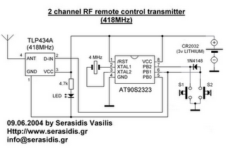
The 3V power supply circuit for the RF remote control utilizes the AT90S2323 microcontroller, which is well-suited for low-power applications. The circuit typically includes a voltage regulator to ensure stable output, capacitors for filtering, and a diode for reverse polarity protection.
The AT90S2323 is an 8-bit microcontroller that operates at a maximum clock frequency of 20 MHz, making it capable of handling various tasks in remote control applications. The microcontroller can interface with RF transmission modules, allowing for wireless communication at a baud rate of 2400 bps, which is sufficient for basic control signals.
In the schematic, the power supply section includes a battery input connected to a voltage regulator, which steps down the voltage to 3V. The output of the regulator is decoupled with capacitors to filter any noise, ensuring that the microcontroller operates reliably. The AT90S2323 is connected to the RF transmitter module, which is responsible for sending signals to the remote control receiver.
The circuit may also include additional components such as resistors for current limiting and pull-up configurations, as well as capacitors for timing functions if necessary. The design emphasizes low power consumption to extend battery life, making it ideal for portable applications. The overall layout should ensure minimal interference and optimal performance for RF communication.The following circuit shows about 3V Power Supply For RF Remote Control Circuit. This circuit Based On the AT90S2323 IC. Features: 2400bps .. 🔗 External reference
Related Circuits
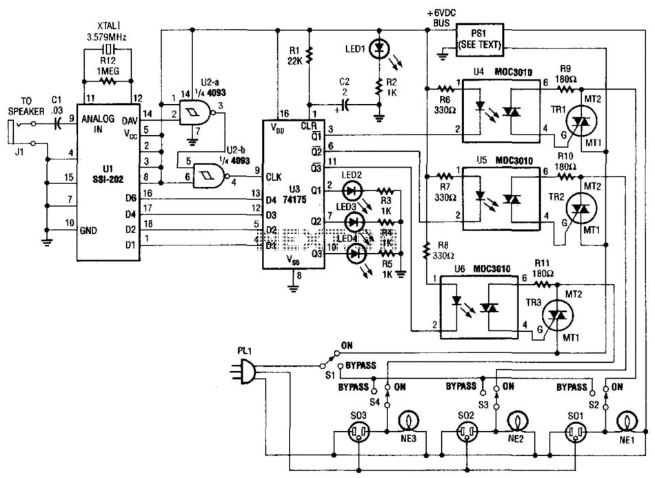
Tones from the DTMF on the telephone line are detected by U1. When a valid tone is received, pin 14 (D More: AV) of U1 produces a positive pulse that is used to drive NAND gates U2A and U2B,...
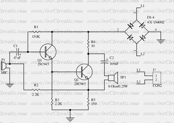
This is the basis of electronics telephone sets. You can use it to replace the talking circuit of an old telephone set with new design, better noise rejection and reliability one. Also you can use it to build a...

The 78W series voltage regulators are designed to handle an input voltage of approximately 35V, while the 24V type can withstand up to 40V. It should be noted that these regulators will not operate effectively with a significant input-output...
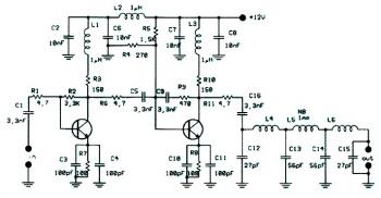
This circuit diagram illustrates a linear FM booster and RF amplifier utilizing the Philips 2N4427 transistor. The RF amplifier is designed to enhance the performance of small FM transmitters and bugs, employing two Philips 2N4427 transistors, delivering approximately 1...
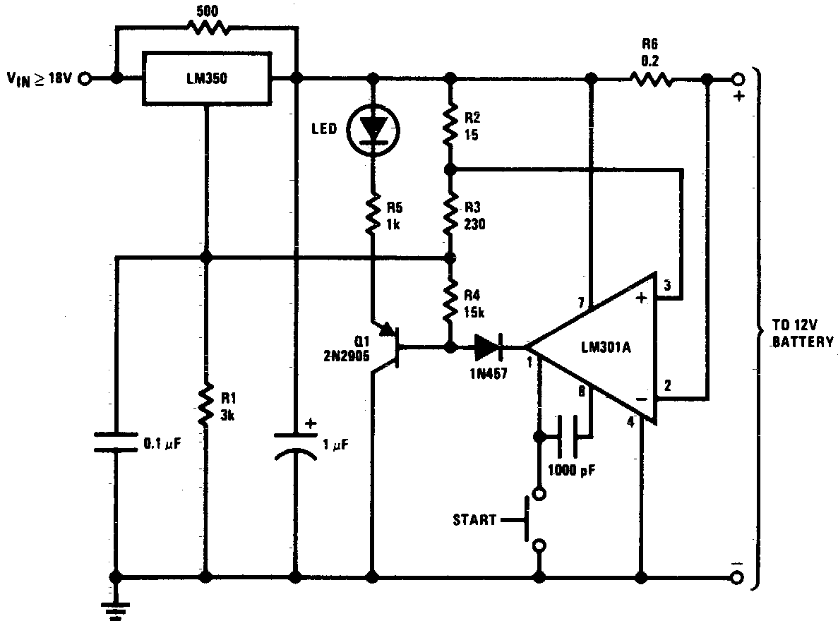
DC 12V Battery Charger Circuit Diagram. This circuit is a high-performance charger for gelled electrolyte lead-acid batteries. The DC 12V battery charger circuit is designed to efficiently charge gelled electrolyte lead-acid batteries, which are commonly used in various applications due...
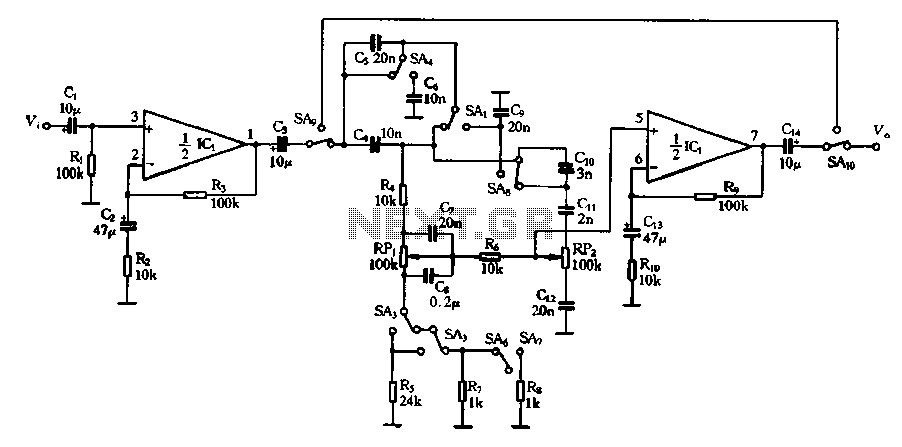
Figure 4-13 illustrates a modified version of a standard attenuated tone control from the pitch selector. It features two amplification stages of amplifiers 10 and Icl utilized as line amplifiers. Capacitor C2 is employed to compensate for tone attenuation...
Warning: include(partials/cookie-banner.php): Failed to open stream: Permission denied in /var/www/html/nextgr/view-circuit.php on line 713
Warning: include(): Failed opening 'partials/cookie-banner.php' for inclusion (include_path='.:/usr/share/php') in /var/www/html/nextgr/view-circuit.php on line 713