
3volt FM TRANSMITTER PROJECT
The tank (LC) circuit is essential for generating the RF carrier waves necessary for FM transmission. The LC circuit, BC547 transistor, and feedback 5pF capacitor together form the oscillator in the circuit. An input signal is not required to sustain the oscillation, as the feedback signal modulates the base-emitter current of the transistor at the resonant frequency, which in turn varies the emitter-collector current at the same frequency. This signal is then fed to the antenna and radiated as radio waves. A 27pF coupling capacitor is placed on the antenna to minimize the impact of the antenna's capacitance on the LC circuit. The term "tank" circuit refers to the LC circuit's ability to store energy for oscillations. In a pure LC circuit (one devoid of resistance), energy is not lost. In an AC environment, only resistive components dissipate electrical energy, while reactive components (capacitors and inductors) merely store energy for later return to the system. It is important to note that the tank circuit does not oscillate solely by applying a DC potential; positive feedback is essential.
The components can be added to the PCB in any sequence. The electret microphone should be installed with the pin connected to its metal casing linked to the negative rail (ground or zero voltage side of the circuit). The coil should measure approximately 3mm in diameter and consist of 5 turns using tinned copper wire with a diameter of 0.61mm. After soldering the coil into place, the turns should be spread apart by about 0.5 to 1mm to prevent contact. The spacing is not critical, as tuning of the transmitter will be achieved using the trim capacitor. A fixed value capacitor, such as 47pF, may be used in place of the trim capacitor; however, this would require varying the coil spacing to adjust the transmitter frequency, affecting the inductance of the LC circuit instead of the capacitance. The circuit can be switched on and off by connecting or disconnecting the batteries. A half or quarter wavelength antenna (a length of wire) should be connected to the antenna point, with lengths of 150 cm and 75 cm corresponding to an FM frequency of 100 MHz. The transmitter should be positioned about 10 feet from an FM radio set to approximately 89-90 MHz. The tuning process involves spreading the coil windings apart by around 1mm and ensuring that no windings are in contact. A small screwdriver can be used to adjust the trim capacitor, with the screwdriver removed after each adjustment to prevent stray capacitance from affecting the LC circuit. If difficulties arise in locating the transmitting frequency, assistance from another person to adjust the FM dial can be beneficial. One full turn of the trim capacitor covers its entire capacitance range from 6pF to 45pF, with the normal FM band tuning over about one-tenth of the full range. Adjustments should be made in steps of 5 to 10 degrees to facilitate tuning.
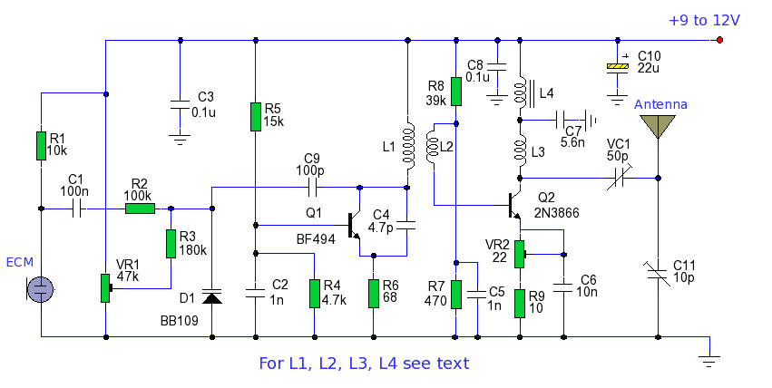
The requirement for at least 10 feet of separation between the FM transmitter and the radio is due to the emission of harmonics by the transmitter; it does not emit on a single frequency but rather on several frequencies close to one another. Following the outlined procedure should simplify the process of locating the transmitting frequency. This project serves as an excellent introduction to various fundamental electronics concepts, including Class C amplifiers, FM transmission, VHF antennas, positive and negative feedback, stray capacitance, crystal-locked oscillators, and signal attenuation. The simple half-wave antenna used in this project is not the most efficient; improved performance can be achieved by connecting a dipole antenna using 50-ohm coaxial cable, with one lead connected to the antenna point and the other to the ground. Experimentation with 6V or 9V power sources may increase the transmitter's range. Additionally, reducing the 22K resistor to 10K can enhance sensitivity. It is important to note that this FM transmitter is not suitable for carrying on the body, as it is sensitive to external capacitance, causing frequency drift based on proximity to the transmitter. Stray capacitance is automatically incorporated into the tank circuit's capacitance, which can shift the transmitting frequency.This project provides the schematic and the parts list needed to construct a 3V FM Transmitter. This FM transmitter is about the simplest and most basic transmitter to build and have a useful transmitting range. It is surprisingly powerful despite its small component count and 3V operating voltage. It will easily penetrate over three floors of an apartment building and go over 300 meters in the open air. It may be tuned anywhere in the FM band. Or it may be tuned outside the commercial M band for greater privacy. (Of course this means you must modify your FM radio to be able to receive the transmission or have a broad-band FM receiver. ) The output power of this FM transmitter is below the legal limits of many countries (eg, USA and Australia).
However, some countries may ban ALL wireless transmissions without a licence. It is the responsibility of the constructor to check the legal requirements for the operation of this kit and to obey them. The circuit is basically a radio frequency (RF) oscillator that operates around 100 MHz. Audio picked up and amplified by the electret microphone is fed into the audio amplifier stage built around the first transistor.
Output from the collector is fed into the base of the second transistor where it modulates the resonant frequency of the tank circuit (the 5 turn coil and the trimcap) by varying the junction capacitance of the transistor. Junction capacitance is a function of the potential difference applied to the base of the transistor.
The tank circuit is connected in a Colpitts oscillator circuit. The electret microphone: an electret is a permanently charged dielectric. It is made by heating a ceramic material, placing it in a magnetic field then allowing it to cool while still in the magnetic field. It is the electrostatic equivalent of a permanent magnet. In the electret microphone a slice of this material is used as part of the dielectric of a capacitor in which the diaphram of the microphone formsone plate.
Sound pressure moves one of its plates. The movement of the plate changes the capacitance. The electret capacitor is connected to an FET amplifier. These microphones are small, have excellent sensitivity, a wide frequency response and a very low cost. First amplification stage: this is a standard self-biasing common emitter amplifier. The 22nF capacitor isolates the microphone from the base voltage of the transistor and only allows alternating current (AC) signals to pass.
The tank (LC) circuit: every FM transmitter needs an oscillator to generate the radio Frequency (RF) carrier waves. The tank (LC) circuit, the BC547 and the feedback 5pF capacitor are the oscillator in the Cadre. An input signal is not needed to sustain the oscillation. The feedback signal makes the base-emitter current of the transistor vary at the resonant frequency. This causes the emitter-collector current to vary at the same frequency. This signal fed to the aerial and radiated as radio waves. The 27pF coupling capacitor on the aerial is to minimise the effect of the aerial capacitance on the LC circuit.
The name tank` circuit comes from the ability of the LC circuit to store energy for oscillations. In a pure LC circuit (one with no resistance) energy cannot be lost. (In an AC network only the resistive elements will dissipate electrical energy. The purely reactive elements, the C and the L simply store energy to be returned to the system later. ) Note that the tank circuit does not oscillate just by having a DC potential put across it. Positive feedback must be provided. (Look up Hartley and Colpitts oscillators in a reference book for more details. ) Components may be added to the PCB in any order. Note that the electret microphone should be inserted with the pin connected to the metal case connected to the negative rail (that is, to the ground or zero voltage side of the circuit).
The coil should be about 3mm in diameter and 5 turns. The wire is tinned copper wire, 0. 61 mm in diameter. After the coil in soldered into place spread the coils apart about 0. 5 to 1mm so that they are not touching. (The spacing in not critical since tuning of the Tx will be done by the trim capacitor. It is quite possible, but not as convenient, to use a fixed value capacitor in place of the trimcapacitor say 47pF and to vary the Tx frequency by simply adjusting the spacing of the coils. That is by varying L of the LC circuit rather than C. ) Adding and removing the batteries acts as a switch. Connect a half or quarter wavelength antenna (length of wire) to the aerial point. At an FM frequency of 100 MHz these lengths are 150 cm and 75 cm respectively. Place the transmitter about 10 feet from a FM radio. Set the radio to somewhere about 89 90 MHz. Walk back to the FM transmitter and turn it on. Spread the winding of the coil apart by approximately 1mm from each other. No coil winding should be touching another winding. Use a small screw driver to tune the trim cap. Remove the screwdriver from the trim screw after every adjustment so the LC circuit is not affected by stray capicitance.
Or use a plastic screwdriver. If you have difficulty finding the transmitting frequency then have a second person tune up and down the FM dial after every adjustment. One full turn of the trim cap will cover its full range of capacitance from 6pF to 45pF. The normal FM band tunes in over about one tenth of the full range of the tuning cap. So it is best to adjust it in steps of 5 to 10 degrees at each turn. So tuning takes a little patience but is not difficult. The reason that there must be at least 10 ft. separation between the radio and the FM transmitter is that the FM transmitter emits harmonics; it does not only emit on one frequency but on several different frequencies close to each other.
You should have little difficulty in finding the Tx frequency when you follow this procedure. It should already be clear from the above circuit description that there is a surprising amount of electronics which may be learnt from this deceptively simple kit. Here is a list of some advanced topics in electronics which can be demonstrated or have their beginnings in this project: Class C amplifiers; FM transmission; VHF antennas; positive and negative feedback; stray capacitance; crystal-locked oscillators; signal attenuation The simple halfwave antenna used in the project is not the most efficient.
Greater efficiency may be gained by connecting a dipole antenna using 50 ohm coaxial cable. Connect one lead to the Antenna point and the other to the earth line. You may experiment using 6V or 9V with the circuit to see how this increases the range of the transmitter. The sensitivity may be increased by lowering the 22K resistor to 10K. Try it and see. Note that this FM transmitter is not suitable for use on your body, for example, in your pocket. This is because it is affected by external capacitance and the transmitting frequency drifts depending how close you are to it.
Stray capacitance is automatically incorporated into the capacitance of the tank circuit which will shift the transmitting frequency. 🔗 External reference
Related Circuits
The circuit for a powerful AM transmitter using ceramic resonator/filter of 3.587 MHz is presented here. Resonators/filters of other frequencies such as 5.5 MHz, 7 MHz and 10.7 MHz may also be used. Use of different frequency filters/resonators will...
Two circuits for laser transmitters are described. The first circuit utilizes a simple laser pointer module, with 3 or 5mW devices functioning effectively. Higher power units are often imported from the USA or Hong Kong compared to UK approved...
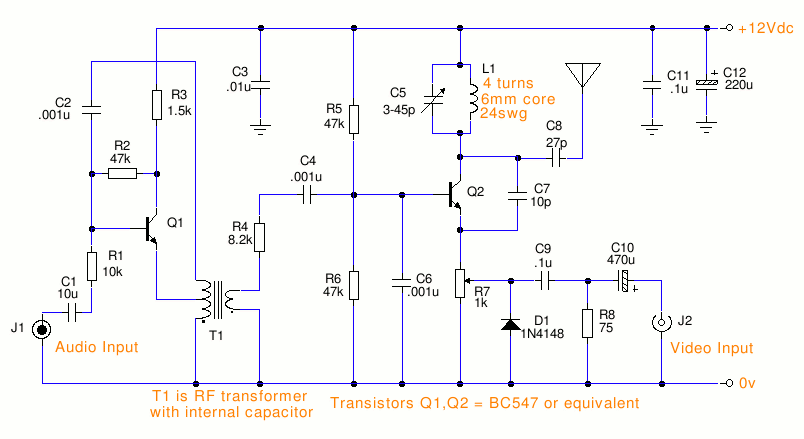
This is a small TV transmitter circuit that transmits in VHF, utilizing negative sound modulation and PAL video modulation. It is suitable for countries that use the B and G system. T1 refers to a type of transformer. The...
The power output of many transmitter circuits is low due to the absence of power amplifier stages. The transmitter circuit presented here includes an additional RF power amplifier stage after the oscillator stage, which elevates the power output to...

This is a design circuit diagram of a versatile FM transmitter. This circuit does not include a coil and is simple and easy to assemble. It operates based on gate logic concepts. The circuit features a buffer gate N1...
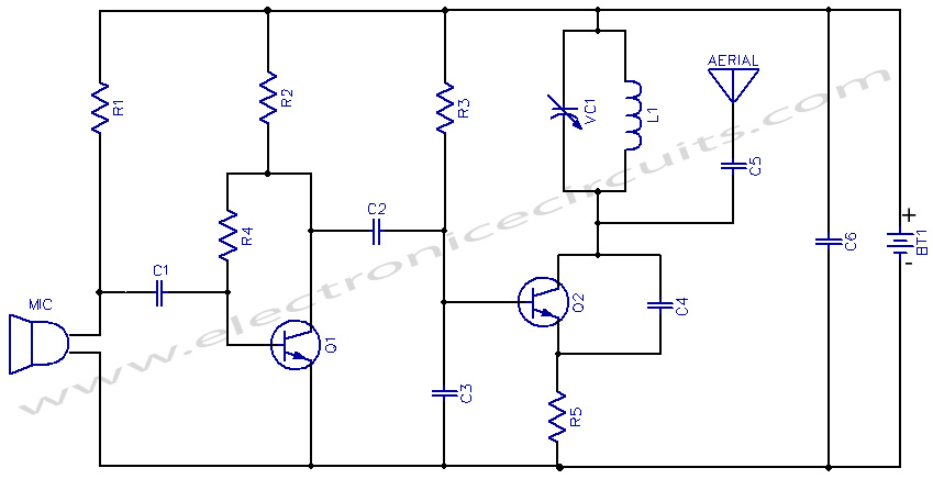
The AM transmitter circuit consists of an audio amplifier and an RF oscillator. The oscillator is constructed around transistor Q1 and its associated components. The tank circuit, which includes inductor L1 and variable capacitor VC1, is tunable from approximately...