
4-wire resistive touch screen interface circuit with ADS7846
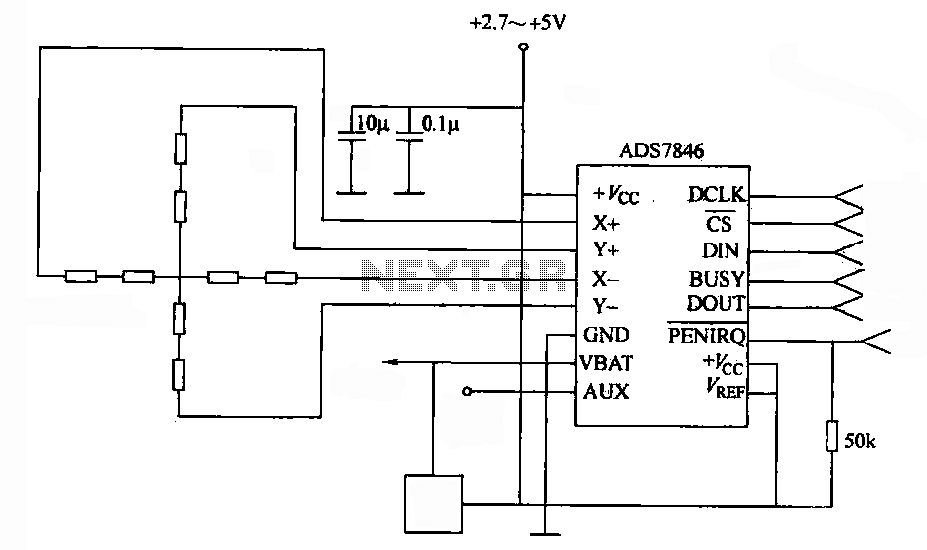
The 4-wire resistive touch screen operates by detecting pressure applied to the screen's surface. It consists of two conductive layers separated by a thin insulating layer. When pressure is applied, these layers make contact, creating a voltage divider that varies based on the location of the touch. The ADS7846 interface circuit plays a crucial role in this process by converting the analog voltages generated at the touch points into digital values that can be interpreted by a microcontroller or other processing unit.
The ADS7846 chip features an integrated analog-to-digital converter (ADC) capable of handling the signals from the touch screen. It employs a successive approximation method, which allows for rapid and accurate conversion of the analog signal to a digital output. The chip also includes electronic switches that facilitate the selection of the X or Y channels based on the touch location, ensuring that the correct voltage levels are sampled.
In operation, the touch screen is connected to the ADS7846 through four main wires: two for the X-axis and two for the Y-axis. The X+ and X- terminals are responsible for the horizontal axis, while the Y+ and Y- terminals handle the vertical axis. When a user touches the screen, the voltage is read from the corresponding terminal, and the ADS7846 processes this voltage to determine the precise coordinates of the touch event.
The output from the ADS7846 is typically in the form of digital coordinates (X, Y), which can be utilized by various applications, including user interfaces and graphical displays. The linearity of the output values ensures that the touch response is accurate, thereby enhancing the user experience. Overall, the combination of the resistive touch screen and the ADS7846 interface circuit provides an effective solution for touch-based input in electronic devices.4-wire resistive touch screen. ADS7846 interface circuit. ADS7846 analog chip contains electronic switches and successive approximation A / D converter. Switched by the analog switch chip, the X + (or Y +) positive supply termination ( ), x- (or Yr) grounded (CND), the Y + (or X +) terminal and Y- (or X- ) terminal to the difference in the form of movable receiving a / D converter input. Pen contacts the touch screen at different locations, by Y + (or X +) terminal input to the on-chip A / D converter different voltage values within the input voltage through the chip A / D conversion after the stroke to give Y points (or x) output value, and the output value of the stroke position is approximately linear.
Therefore, ADS7846 output value of X and Y (ie coordinates) will be able to describe the strokes on the touch screen point of location.
Related Circuits
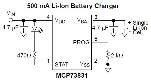
Nokia BL-4C and BL-5C are 3.7V, 700-1000mAh (various) lithium-ion batteries that have three terminals. These terminals include a positive terminal, a ground, and a BSI (Battery Status Indicator) terminal, which presents a fixed resistance value that needs to be...
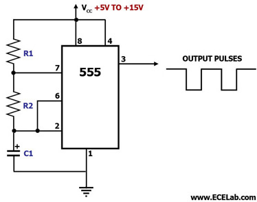
This circuit diagram illustrates the configuration of a 555 timer integrated circuit (IC) as an astable multivibrator. An astable multivibrator is a timing circuit characterized by unstable 'low' and 'high' states. Consequently, the output of an astable multivibrator continuously...
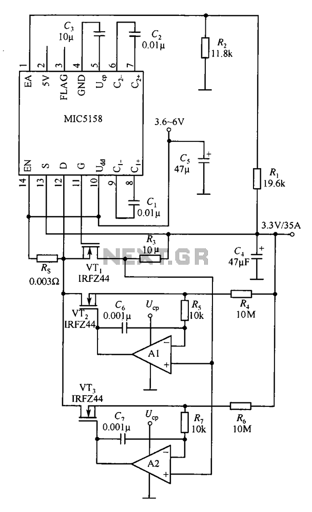
The MIC5158 is designed to manage tasks by controlling multiple external N-channel MOSFETs in parallel, which enables high current or high power output for a linear regulator circuit. This is illustrated in the accompanying figure. The operational amplifier circuit...
Automatic fan control circuit. This circuit turns a 12V DC fan or CPU fan on or off based on temperature readings. The temperature can be adjusted using VR1. The automatic fan control circuit operates by monitoring the temperature of...
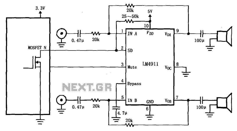
The circuit for the LM4911 demonstrates different power conduction times. It utilizes a controller, specifically the MOSFET LM4911 shutdown control (SD) terminal, to regulate the on-time of the amplifier. The LM4911 is a power amplifier designed for audio applications, providing...
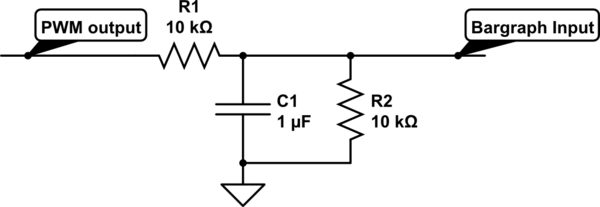
For a project, there is a need to display a progress bar representing the activity performed by a microcontroller unit (MCU). A bar graph display is intended for this purpose; however, the bar graph display driver IC, LM3914, requires...
Warning: include(partials/cookie-banner.php): Failed to open stream: Permission denied in /var/www/html/nextgr/view-circuit.php on line 713
Warning: include(): Failed opening 'partials/cookie-banner.php' for inclusion (include_path='.:/usr/share/php') in /var/www/html/nextgr/view-circuit.php on line 713