
400 Hz SERVO AMPLIFIER
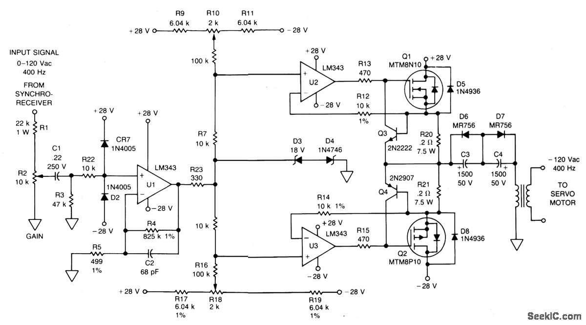
The circuit described involves several key components that work together to amplify and control an input signal for driving a servo motor. The initial signal, originating from either a synchro receiver or a potentiometer, is processed by operational amplifier U1. This amplifier is designed to boost the input signal while ensuring that the output does not exceed certain voltage levels, which is achieved through the inclusion of zener diodes D3 and D4. These diodes are connected in reverse parallel configuration, providing a protective clamping mechanism for the output, thus preventing potential damage to subsequent components from overvoltage conditions.
Following amplification, the processed signal is directed to operational amplifiers U2 and U3. These amplifiers are configured to further manipulate the signal before it is sent to the gates of transistors Q1 and Q2. The role of these transistors is critical, as they act as switches that control the flow of current to the load, which in this case is the servo motor.
Transistors Q3 and Q4 function as current limiters for their respective n-channel and p-channel MOSFETs (MTM8N10 and MTM8P10). This configuration ensures that the transistors operate within safe current limits, thereby enhancing the reliability and longevity of the circuit. The fast response time of Q3 and Q4 is essential for applications that require quick adjustments to the motor's operation, such as in servo control systems.
Capacitors C3 and C4 are strategically placed in the circuit to manage DC offset levels. By filtering out unwanted DC components, these capacitors help maintain the integrity of the AC signal driving the servo motor, thus simplifying the overall circuit design by negating the need for precise DC offset adjustments.
Finally, transformer T1 plays a pivotal role in stepping up the output voltage to 120 V, which is necessary for the operation of the 400 Hz servo motor. The transformer is designed to handle the specific frequency and voltage requirements of the motor, ensuring that it operates efficiently and effectively within the desired parameters. Overall, this circuit design illustrates a well-integrated approach to signal amplification and motor control, utilizing a combination of operational amplifiers, transistors, and passive components to achieve the desired functionality.The signal from a synchro receiver or a variable resistive cam follower (potentiometer) is boosted by operational amplifier U1, whose output swing is limited by back-to-back zeners D3 and D4. The signal is then applied to operational amplifiers U2 and U3, which drive the gates of Q1 and Q2 respectively.
The npn transistor (Q3) is a fast current li miter for the n-channel MTM8N10; a pnp transistor (Q4) performs the same function for the p-channel MTM8P10. Capacitors C3 and C4 eliminate the need for accurate dc offset zeroing. T1 steps up the output voltage to 120 V for the 400 Hz servo motor. 🔗 External reference
Related Circuits
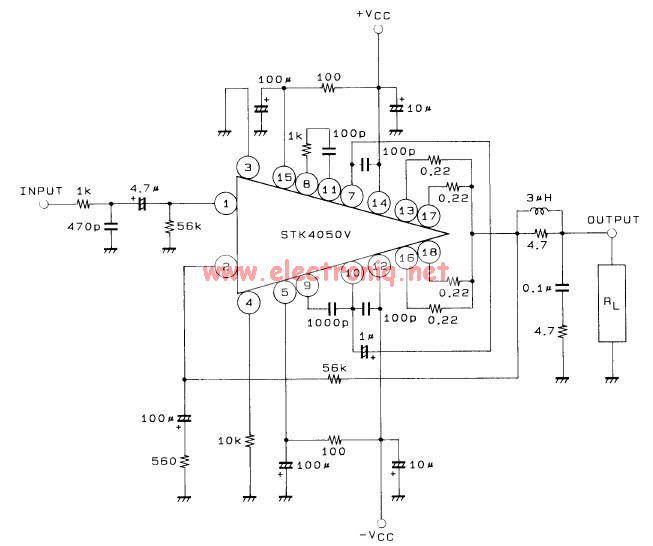
This 200-watt audio amplifier circuit diagram is based on the STK4050V high-power audio amplifier IC, designed to deliver up to 200 watts of audio power on a single channel. The STK4050V 200-watt audio amplifier circuit is pin-compatible with other...
The objective of this design is to create a Combo amplifier that is reminiscent of those commonly found in the 1960s and 1970s. It is particularly effective as a guitar amplifier but is also suitable for various electronic musical...
This is a simple phono preamplifier circuit diagram. In recent years, following the introduction of CDs, vinyl recordings have almost disappeared. Nevertheless, a phono preamplifier remains useful for listening to old vinyl discs from a well-preserved collection. This simple...
The description pertains to a specific type of preamplifiers that are designed to amplify the low output of Moving coil heads, enabling their drive to an input PHONO [RIAA] of a preamplifier. Moving coil heads present certain challenges that require...
The original description discusses an application that is reputed for its high-quality sound. This superior sound quality is attributed to the operation of the entrance transistors at Class A. The sound quality is largely dependent on IC1, which needs to...
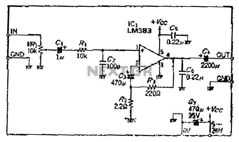
A closed-loop amplification circuit is designed to achieve a magnification of 100 times (40 dB). To ensure stable operation, particularly with high input signals, a variable resistor (VRi) is incorporated in the secondary circuit for attenuation. The feedback resistor...