40M-cw-transceiver

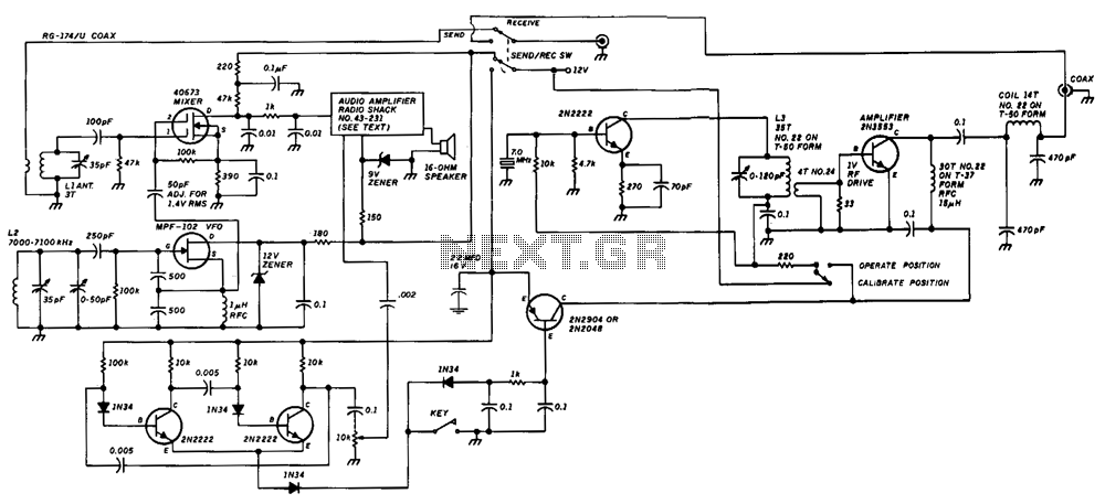
The unit consists of a direct conversion receiver and a 1-W transmitter. The direct conversion receiver's voltage-controlled oscillator (VFO) is tuned slightly off frequency from the incoming signal. This frequency difference generates a clean, strong, and solid audio tone signal. The resonant frequency of the transmitter VFO can be detected using the grid dip oscillator (GDO) as a field-strength meter. Due to the large capacitance in the Colpitts VFO, the tuning coil will have fewer turns than the mixer coil. The specified capacitance should be used for the VFO gate to ground and to the coil. Additionally, 1.4-V rms is required on pin 2 of the mixer to obtain a good signal from the VFO. The 1000-ohm resistor and 0.01 µF capacitors function as an RF filter from the mixer output.
The circuit described integrates a direct conversion receiver with a 1-W transmitter, focusing on efficient signal processing and transmission. The direct conversion receiver employs a VFO that is intentionally tuned slightly off from the frequency of the incoming signal. This configuration is critical as the frequency offset facilitates the generation of an audio tone signal characterized by its clarity and strength, which is essential for effective audio output.
The resonant frequency of the transmitter's VFO is determined using a GDO, which serves as a field-strength meter. This method allows for precise tuning, ensuring optimal performance of the transmitter. The Colpitts VFO design is notable for its large capacitance, which necessitates a tuning coil with fewer turns compared to the mixer coil. This design choice helps maintain the stability and performance of the oscillator.
Capacitance values specified for the VFO gate to ground and to the coil are pivotal in achieving the desired operational characteristics. The requirement of 1.4-V rms on pin 2 of the mixer is crucial for ensuring that a robust signal is derived from the VFO. This voltage level is a key parameter that influences the overall performance of the mixer, impacting the quality of the output signal.
The inclusion of a 1000-ohm resistor and a 0.01 µF capacitor at the mixer output serves a dual purpose. These components act as an RF filter, effectively suppressing unwanted high-frequency noise and ensuring that the output signal maintains its integrity. The filter design is essential for enhancing the overall functionality of the circuit, allowing for clearer audio signals and improved transmission quality.
In summary, this electronic schematic features a well-integrated system that emphasizes careful tuning, filtering, and signal processing to achieve optimal performance in both receiving and transmitting applications.The unit consists of a direct conversion receiver and 1-W transmitter. The direct conversion receiver VFO is tuned just off frequency from the incoming signal. This difference in frequency produces a clean, strong, and solid audio tone signal. Detect the resonant frequency of the transmitter VFO by using the GDO as a field-strength meter. Because of the large capacitance in the Colpitts VFO, the tuning coil will have fewer turns than the mixer coil. Use the capacitance shown for the VFO gate to ground and to the coil. It will effect the frequency and output. You"ll need 1.4-V rms on pin 2 of the mixer to get a good signal from the VFO. The 1000-0 resistor and 0. 01-!iF capacitors act as an rf filter from the mixer output.