
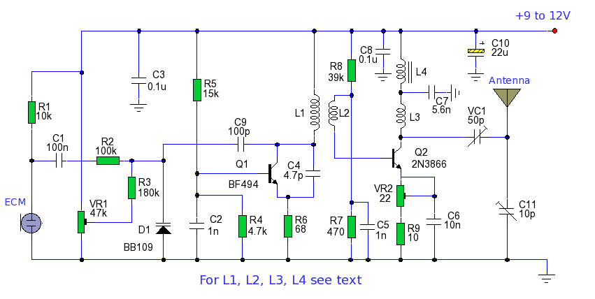
40W FM transmitter with valve EL34
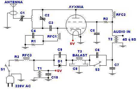
The circuit described is a basic audio amplifier system designed to operate with a 220V AC power supply. It employs a 220V to 6V transformer (T1) for isolation and safety, followed by a secondary transformer (T2) configured to handle an output power of approximately 4 to 8 watts. The use of R3 is optional; omitting it increases the output power but also raises the 50Hz hum, indicating a trade-off between power and noise levels.
The circuit utilizes capacitors C1 and C2 to manage frequency response and adapt the aerial resistance, ensuring clarity in audio reception. C1 is a 50pF trimmer capacitor, allowing for fine-tuning of the circuit to optimize audio quality. C2, a 30pF trimmer capacitor, serves to regulate the frequency, which is crucial for maintaining audio fidelity.
The resistors R1, R2, and R3 are specified with their respective ratings: R1 is a 15kΩ, 2W resistor; R2 is a 1kΩ, 10W resistor; and R3 is also a 1kΩ, 10W resistor, which can be replaced with a short circuit for maximum output power. The circuit includes several additional capacitors (C3 through C10) with various voltage ratings, contributing to the stability and filtering of the power supply and audio signal.
Inductors RFC1, RFC2, and RFC3 are air-core inductors, constructed with 15 coils of 8mm diameter wire, enhancing the circuit's performance by minimizing electromagnetic interference. The BY127 rectifier diode (D1) is employed for converting AC to DC, ensuring the circuit operates efficiently.
The audio input can be sourced from a cassette player or other powerful audio devices. If a microphone is used, it should be preceded by an amplifier to achieve the desired output power of approximately 8W. The output stage includes a vacuum tube (Lamp) such as the 807 SYLV USA or EL34, which is capable of handling the required audio amplification.
An antenna is included in the design, specified as a simple dipole of length L/2, where L represents the wavelength, allowing for effective transmission and reception of audio signals. The circuit features two switches: S1 serves as the main power switch, while S2 is a secondary switch for power control during operation, which should be closed after the circuit is energized.
This schematic provides a foundational understanding of the audio amplifier circuit, highlighting its key components and their roles in delivering amplified audio output while managing noise and frequency response effectively.The catering better it does not become at straight line from the network 220V but via transformer 220V/220V of isolation and safety 1A. When does not exist the R3, the force of expense is bigger, but respectively is increased also the hum 50Hz, because the simplicity of designing.
With the C2 we regulate the frequency. With the C1 we adapt the resistance of aerial (practically him we regulate so that it is heard our voice in the radio as long as you become cleaner). The control (Audio In) can become from a kasseto'fwno or other powerful source. If it is microphone it will be supposed precedes amplifier so that it acquires a force of order of 8W roughly. R1 15KW/2W R2 1KW/10W R3 1KW/10W (for biggest force in the exit you replace with short-circuit). C1 50pF trimmer C2 30pF trimmer C3 22pF/4KV C4, c6, c9 10nF/1KV C5, c7 1nF/1KV C8 100mF+100mF/450V (Double electrolytic) C9, c10 10nF RFC1, rfc2, rfc3 air Inductors: 15 coils diameter 8mm, from wire 1mm.
T1 Transformer 220V/6V-1A T2 Transformer of configuration with being first 4 or 8W T3 Inductor with core ferrite (externally it resembles with small transformer but has a turn only). D1 BY127 rectifier Lamp 807 SYLV USA or EL34 or equivalent ANTENNA Simple dipole L/2. (L= wave length) S1 Main switch of catering. S2 Switch of catering of rise (him we close after zestacej' the thread). 🔗 External reference
Related Circuits
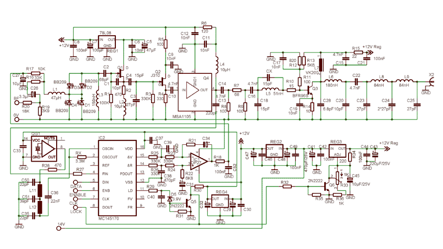
In order to simplify the transmitter design, we've used the new pll circuit from Motorola: the MC145170. This PLL includes the prescaler and a serial standard bus called SPI. We advise to use the P2 version that fixes some...
There are various techniques to ensure the stability of an FM transmitter, preventing frequency drift as the battery voltage decreases. The RF circuit illustrated below is a compact and stable FM transmitter that utilizes a zener diode to maintain...
This circuit is a basic design that includes indicator LEDs and appropriate resistor values. A dotted line indicates that the IR LED is connected to the circuit via a length of wire (in this case, a telephone cable). The...
The power output of many transmitter circuits is low due to the absence of power amplifier stages. The transmitter circuit presented here includes an additional RF power amplifier stage after the oscillator stage, which elevates the power output to...
This small transmitter utilizes a Hartley type oscillator. Typically, the capacitor in the tank circuit would connect at the base of the transistor; however, at VHF frequencies, the base-emitter capacitance of the transistor behaves like a short circuit, effectively...
This compact video transmitter is highly effective for short-distance video surveillance, operating efficiently up to 100 meters. It can be paired with either a black-and-white or infrared camera module, providing excellent image quality on standard color or black-and-white televisions....
Warning: include(partials/cookie-banner.php): Failed to open stream: Permission denied in /var/www/html/nextgr/view-circuit.php on line 713
Warning: include(): Failed opening 'partials/cookie-banner.php' for inclusion (include_path='.:/usr/share/php') in /var/www/html/nextgr/view-circuit.php on line 713