
43 dB antenna amplifier circuit diagram
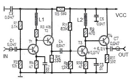
The antenna amplifier circuit is designed to enhance signal strength within the specified frequency range, making it suitable for various applications such as broadcasting, telecommunications, and amateur radio. The choice of transistors, such as BF183 or BF200, is critical as they provide the necessary gain and bandwidth characteristics required for efficient operation.
The circuit typically consists of a common-source or common-emitter configuration, depending on the design preference. This configuration allows for significant voltage gain while maintaining low distortion levels, as indicated by the low 3 dB non-linearity. The amplifier's input and output impedance of 75 ohms is standard for RF applications, ensuring compatibility with typical antenna systems and transmission lines.
Power supply considerations are also essential in the design of this amplifier. The low current requirement of 20 mA allows for the use of compact power supplies, which can be beneficial in portable or battery-operated applications. Additionally, proper bypass and coupling capacitors should be implemented to ensure stability and prevent oscillations, which can degrade performance.
Overall, this antenna amplifier circuit is a robust solution for enhancing RF signals across a wide frequency range while maintaining efficiency and low power consumption.This antenna amplifier is very useful for 35kHz-150Mhz frequency band. This antenna amplifier circuit is based on transistors and has a low 3dB non-linearity and a high gain of 43 dB. The input and output impedance for this rf amplifier is 75 ohms. All used transistors are of the same type and can be BF183, BF200 or other similar type. The tot al consumption of this rf amplifier is very low, the circuit will need only 20 mA. 🔗 External reference
Related Circuits
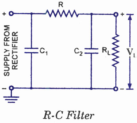
The disadvantages of pi-filters include higher costs, increased weight, larger size, and the external magnetic field generated by the series inductor. These issues can be mitigated by substituting the series inductor with a series resistor, referred to as an...
This is a highly sensitive envelope detector designed for AM radio applications. The circuit, illustrated in Figure 1, enables linear detection of weak signals with a modulation depth of 80-85%. The first stage (VT1) functions as a common-emitter amplifier...
A rear fog lamp is mandatory for trailers and caravans to enhance visibility during foggy conditions. When the fog lamp is activated, the fog lamp of the towing vehicle must be turned off to prevent distracting reflections. To achieve...
This is a simple transistor tester circuit that can be utilized to test both NPN and PNP transistors. The voltage source consists of a 6V power supply, which is derived from a step-down transformer that converts 230V AC to...

Often, there is a need for an additional telephone ringer in an adjoining room to be alerted about incoming calls. For instance, if the telephone is situated in the drawing room, an extra ringer may be required in the...
The goal is to create a small light that is activated by motion and stays illuminated for 20 seconds before turning off. For example, when the light is picked up, it illuminates, and when placed back down, it remains...
Warning: include(partials/cookie-banner.php): Failed to open stream: Permission denied in /var/www/html/nextgr/view-circuit.php on line 713
Warning: include(): Failed opening 'partials/cookie-banner.php' for inclusion (include_path='.:/usr/share/php') in /var/www/html/nextgr/view-circuit.php on line 713