
45 Watt Class-B Audio Power Amplifier
The described circuit utilizes a discrete operational amplifier designed to drive a complementary BJT output stage configured for Class B operation. The use of discrete components allows for higher voltage ratings and customization of the amplifier's characteristics, which is particularly advantageous for high-power audio applications.
In the circuit, the op-amp operates in conjunction with the output transistors to manage the current flow effectively. For low output currents, the op-amp is responsible for supplying the output current entirely, thus avoiding the inefficiencies associated with the output transistors. As the output current requirement increases, the output transistors begin to conduct, taking over the output current supply while the op-amp contributes minimally, as defined by the formula 0.7/R11. This design choice minimizes crossover distortion, a common issue in amplifiers, by ensuring that the quiescent current from the op-amp keeps the external transistors biased adequately.
The transformer specifications of 25 + 25V or 24 + 24V with a power rating of 100/120VA are critical for providing the necessary power to achieve the desired output levels of 45W into 8 Ohms and 69W into 4 Ohms. The design emphasizes low distortion, ensuring that audio signals remain clear and accurate, even at higher power levels.
This amplifier circuit is versatile and can be applied in various audio applications, including as a high-fidelity audio amplifier or as a dedicated guitar or bass amplifier. Its rugged construction and straightforward design make it suitable for both professional and amateur audio environments, enhancing the overall audio experience.These goals were achieved by using a discrete-components op-amp driving a BJT complementary common-emitter output stage into Class B operation. In this way, for small output currents, the output transistors are turned off, and the op-amp provides all of the output current.
At higher output currents, the power transistors conduct, and the contribution of the op-amp is limited to approximately 0. 7/R11. The quiescent current of the op-amp biases the external transistors, and hence greatly reduces the range of crossover. The idea sprang up from a letter published on Wireless World, December 1982, page 65 written by N. M. Allinson, then at the University of Keele, Staffordshire. In this letter, op-amp ICs were intended as drivers but, as supply voltages up to +/- 35V are required for an amplifier of about 50W, the use of an op-amp made of discrete-components was then considered and the choice proved rewarding.
The discrete-components op-amp is based on a Douglas Self design. Nevertheless, his circuit featured quite obviously a Class A output stage. As for proper operation of this amplifier a Class B output stage op-amp is required, the original circuit was modified accordingly. Using a mains transformer with a secondary winding rated at the common value of 25 + 25V (or 24 + 24V) and 100/120VA power, two amplifiers can be driven at 45W and 69W output power into 8 and 4 Ohms respectively, with very low distortion (less than 0.
01% @ 1kHz and 20W into 8 Ohms). This simple, straightforward but rugged circuit, though intended for any high quality audio application and, above all, to complete the recently started series of articles forming the Modular Preamplifier Control Center, is also well suited to make a very good Guitar or Bass amplifier. Enjoy! 🔗 External reference
Related Circuits
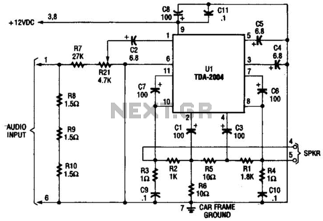
Only one channel of this circuit is shown. The other is practically identical. The input to the circuit, taken from the speaker output of a car radio, is divided into two paths. In one path, a high-power divider network...
Many antique radios operate on batteries, including tube portables like the Zenith model K-401 and "farm" radios used in rural areas without electrical power. This article provides historical context on battery usage in early radios and offers guidance on...
This compact device serves as a replacement for the input transistors and related circuitry on a single TO-220 style package. A decision was made to substitute the original driver board with a newly fabricated printed circuit board (PCB) designed...
The circuit operates with relevant components highlighted in the manual's draw mode. Figure A presents a circuit schematic, while Figure B illustrates a typical conventional secondary circuit layout. Figure E showcases an improved secondary circuit schematic diagram that incorporates...
All miniature electronic devices operate off batteries. Some of them require higher than the standard battery voltages for efficient operation. If a battery with the specific voltage is unavailable, additional cells must be connected in series to increase the...
A window comparator formed by two operational amplifiers packaged into IC1 is the heart of the circuit below. With this technique, we can detect precisely and symmetrically. The window comparator circuit utilizes two operational amplifiers (op-amps) configured to create a...
Warning: include(partials/cookie-banner.php): Failed to open stream: Permission denied in /var/www/html/nextgr/view-circuit.php on line 713
Warning: include(): Failed opening 'partials/cookie-banner.php' for inclusion (include_path='.:/usr/share/php') in /var/www/html/nextgr/view-circuit.php on line 713