
470 Mw complementary-symmetry audio amplifier
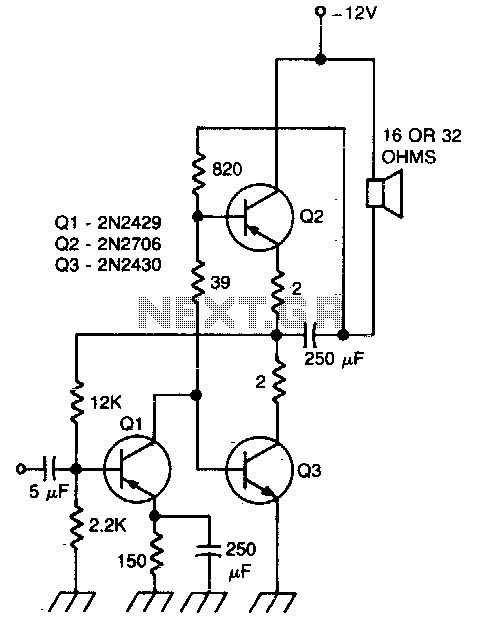
The described circuit is engineered to provide high fidelity audio performance, characterized by minimal distortion and a wide frequency response. The distortion level, being less than 2%, indicates that the circuit is capable of accurately reproducing audio signals without introducing significant artifacts, which is crucial for high-quality audio applications.
The frequency response range of 15 Hz to 130 kHz signifies that the circuit can effectively handle both low and high-frequency signals. The lower limit of 15 Hz ensures that deep bass sounds are reproduced accurately, while the upper limit of 130 kHz allows for the reproduction of high-frequency sounds that can enhance the overall audio experience, including the nuances in music and sound effects.
In practical applications, such a circuit can be utilized in various audio equipment, including amplifiers, mixers, and equalizers. The flat response within 3 dB across the specified frequency range suggests that the circuit does not favor any particular frequency, thereby ensuring a balanced output. This is particularly important in professional audio settings where accurate sound reproduction is essential for mixing and mastering audio tracks.
To achieve these performance metrics, the circuit may incorporate high-quality components such as precision resistors, capacitors, and operational amplifiers, along with careful layout design to minimize noise and interference. Additionally, feedback mechanisms may be employed to stabilize the gain and further reduce distortion. Overall, this circuit design is well-suited for audiophiles and professionals seeking high-performance audio solutions.This circuit has less than 2% distortion and i&flat within 3 dB from 15 Hz to 130 kHz. 🔗 External reference
Related Circuits
18W audio amplifier constructed using transistors. The 18W audio amplifier design utilizes a transistor-based configuration to achieve efficient amplification of audio signals. The circuit typically consists of several stages, including a preamplifier stage, a driver stage, and a power output...
One still designing that it uses in the exit transistor of technology V-mosfet. This transistors to us offer a lot of virtues concerning the simple bipolar transistors, as high speeds, thermic stability, low distortion etc. Beyond this circuit use...
The gain of the low-cost IC is internally fixed at no less than 34 dB (50 times). A unique input stage allows input signals to be referenced to ground. The output is automatically self-centering to one-half the supply voltage...
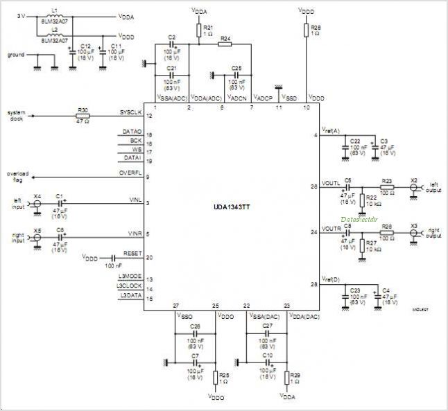
The UDA1350AH is a single-chip IEC 958 audio decoder that features an integrated stereo digital-to-analog converter utilizing bitstream conversion techniques. In addition to the UDA1350AH, which is the fully-featured version packaged in a QFP44, there is also the UDA1350ATS....
This weblog discusses electronic circuit schematics, PCB design, DIY kits, and electronic project diagrams. The subject circuit is a quality preamplifier with a built-in USB DAC designed for the Leachamp power amplifier. The schematic is based on the PCM2902...
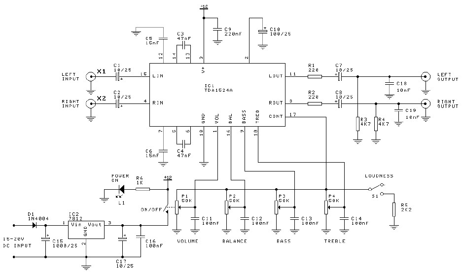
Preamplifier and tone control circuit based on the TDA1524A. The tone control circuit module is included in this preamplifier circuit, allowing for direct connection of the output channels to a stereo power audio amplifier circuit. This RIAA stereo preamplifier...
Warning: include(partials/cookie-banner.php): Failed to open stream: Permission denied in /var/www/html/nextgr/view-circuit.php on line 713
Warning: include(): Failed opening 'partials/cookie-banner.php' for inclusion (include_path='.:/usr/share/php') in /var/www/html/nextgr/view-circuit.php on line 713