
5 band graphic equalizer using LA3600
The LA3600 graphic equalizer circuit is designed to provide precise control over audio frequency ranges, allowing users to tailor sound output according to their preferences. The five bands correspond to specific frequency ranges, typically including bass, mid-bass, midrange, upper midrange, and treble. Each band’s response can be fine-tuned by adjusting the associated potentiometers (R1 to R5), which vary the gain applied to the signal.
The operational amplifier within the LA3600 is configured in a non-inverting arrangement, which is common for equalizer circuits as it maintains a high input impedance and low output impedance, ensuring minimal signal loss. The selected capacitors (C1, C3, C5, C7, and C9) are critical in determining the center frequencies of the bands and should be chosen based on the desired audio characteristics.
The input capacitors (C2, C4, C6, C8, C10, and C15) play a significant role in filtering the incoming audio signal, allowing for the desired frequency range to pass while blocking unwanted frequencies. The values of these capacitors can be adjusted to modify the frequency response, particularly enhancing the bass frequencies for a richer sound.
Capacitor C13 acts as a decoupling capacitor, which is essential for stabilizing the power supply to the LA3600, reducing noise and preventing oscillations that could affect performance. The power supply filter capacitor (C14) ensures that any high-frequency noise from the power supply does not interfere with the audio signal.
The output capacitor (C12) is crucial for coupling the processed audio signal to the next stage of the audio system while blocking any DC offset that could damage downstream components. Resistor R6 is included to limit the current supplied to the circuit, protecting the IC from potential overcurrent situations.
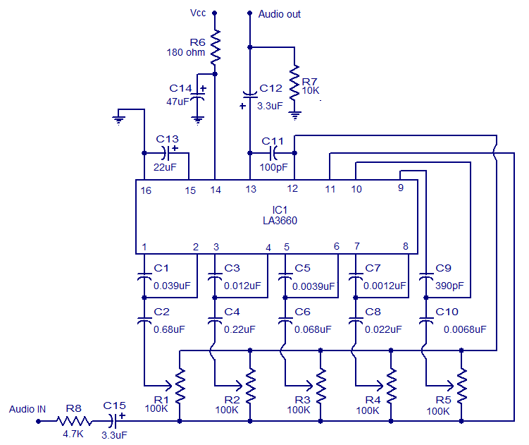
In summary, the LA3600 graphic equalizer circuit is a versatile and effective solution for enhancing audio quality across various applications, providing users with the ability to customize their sound experience through precise frequency adjustments.The graphic equalizer shown here is based on the IC LA3600 from Sanyo Semiconductors. LA 3600 is a single integrated single Op-amp, 5 band graphic equalizer IC which is very suitable for applications like portable stereo, radio sets, home theater systems, car audio systems etc. The LA3600 can be operated from anything between 5 to 15V DC and is ex tremely stable to capacitive loads. In the circuit capacitors C1, C3, C5, C7 and C9 are used to fix the resonance frequency of the corresponding bands. Capacitors C2, C4, C6, C8, C10 and C15 are the input capacitors and increasing the value of these capacitors will increase the low frequency response.
Capacitor C13 is a decoupling capacitor and C14 is a power supply filter circuit. C12 is the output capacitor and resistor R6 limits the supply current. Gain of each band can be adjusted by using the corresponding potentiometers R1 to R5. 🔗 External reference
Related Circuits

An FM and AM transmitter integrated into a compact device utilizing the CD4001 integrated circuit. It broadcasts at 20 MHz for AM and 100 MHz for FM. The described transmitter combines both Frequency Modulation (FM) and Amplitude Modulation (AM) capabilities...
Heavy-duty portable charger for USB devices (phones, iPad, etc.). Have you ever needed to charge your phone on the go? Unable to find a wall socket to charge your iPod?.. The heavy-duty portable charger is designed to provide a reliable...
This circuit is a conventional Pierce type oscillator that utilizes a JFET. It employs fundamental mode crystals and demonstrates decent performance and reliability. The Pierce oscillator is a popular configuration for generating stable oscillations, particularly in applications requiring a stable...
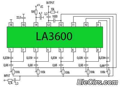
Circuit LA3600 5 Band Equalizer Circuit Schematics. One type of tone control in audio electronics is the graphic equalizer. Graphic equalizers can be categorized into two types: bar and other configurations. The LA3600 circuit is a 5-band graphic equalizer designed...
For beginners in microcontroller projects who are unsure where to start, this project serves as one of the simplest options available. It provides a clear understanding of programming a microcontroller. Often, one may glance at a watch and ponder,...
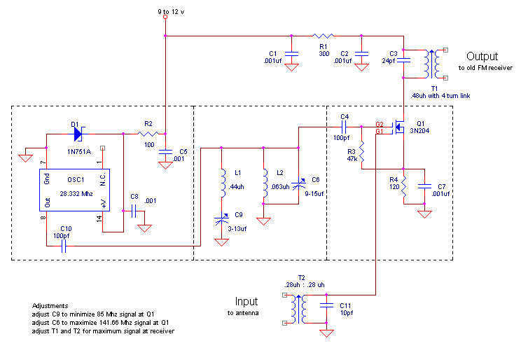
The FM broadcast band was moved immediately after World War II from its original spot just below 50 Mc to the present 88-108 Mc band. Hallicrafters was one company to offer receiving converters for those who had the old...
Warning: include(partials/cookie-banner.php): Failed to open stream: Permission denied in /var/www/html/nextgr/view-circuit.php on line 713
Warning: include(): Failed opening 'partials/cookie-banner.php' for inclusion (include_path='.:/usr/share/php') in /var/www/html/nextgr/view-circuit.php on line 713