
5 channel graphic equalizer by BC548 transistor
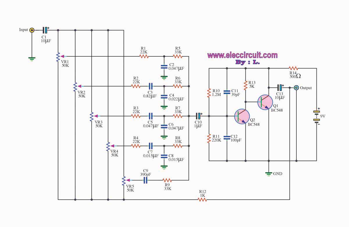
The graphic equalizer circuit functions by providing the ability to adjust specific frequency bands of an audio signal, allowing for tailored sound reproduction. Typically, this circuit consists of multiple band-pass filters, each tuned to a specific frequency range. The output of each filter can be adjusted using potentiometers, which control the gain for that particular frequency band.
The circuit usually comprises operational amplifiers (op-amps) configured as active filters. Each filter section can be designed as a second-order or higher filter to achieve a steeper roll-off and better separation between adjacent frequency bands. The standard configuration may include several bands, such as 31, 15, or 10 bands, covering the audible spectrum from approximately 20 Hz to 20 kHz.
In a typical implementation, the input audio signal is fed into the circuit, and each filter section processes the signal by boosting or attenuating the amplitude of the specific frequency range. The overall output is a composite of all the adjusted signals, providing a customized audio output that compensates for deficiencies in the original audio source or the acoustics of the listening environment.
To ensure optimal performance, components such as resistors and capacitors must be selected with precision, as they determine the center frequency and bandwidth of each filter. Additionally, feedback mechanisms may be employed to stabilize the circuit and reduce distortion, ensuring high fidelity in audio reproduction.
The graphic equalizer circuit is widely used in various applications, including home audio systems, professional sound reinforcement, and music production, making it an essential tool for audio engineers and enthusiasts alike.The graphic equalizer circuit the frequency adjust circuit. For some kinds of audio frequency response is not smooth. The.. 🔗 External reference
Related Circuits

A gyrator is a circuit that utilizes active devices and transistors to emulate an inductor. In this instance, the gyrator comprises a transistor in conjunction with resistors R1, R3, and capacitor C2. Alternatively, a unity gain operational amplifier could...
The modular Portable Mixer design featured on these web pages has gained popularity among many amateurs; however, some users have requested a simpler device primarily for mixing mono signals. This design aims to meet those requirements, incorporating three inputs...
Create an H-Bridge for controlling a DC brushed motor using PWM. One bridge will control one DC motor. The bridge will have three inputs: A, B, and PWM. Inputs A and B will determine the direction of the motor,...
Figure 2-33 (a) illustrates the schematic diagram of a robot approaching an object. When no objects are detected in front of the robot, it moves forward in a straight line. If an object is detected on the left or...
Schematic diagram. A presentation of the element-by-element relationship of all parts of a system. A schematic diagram serves as a crucial tool in electronic design and engineering, representing the interconnections and relationships between various components within a system. It provides...
The circuit was designed to create an audio mixer that can be assembled in modules while providing 6 or more input channels. An audio mixer is a device used to combine multiple audio signals into a single output. The audio...