
5-channel low-power interface circuit programmable sensor signal processor AD7714 and MCS-51 series microcontroller
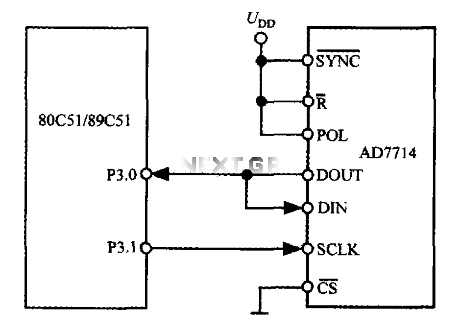
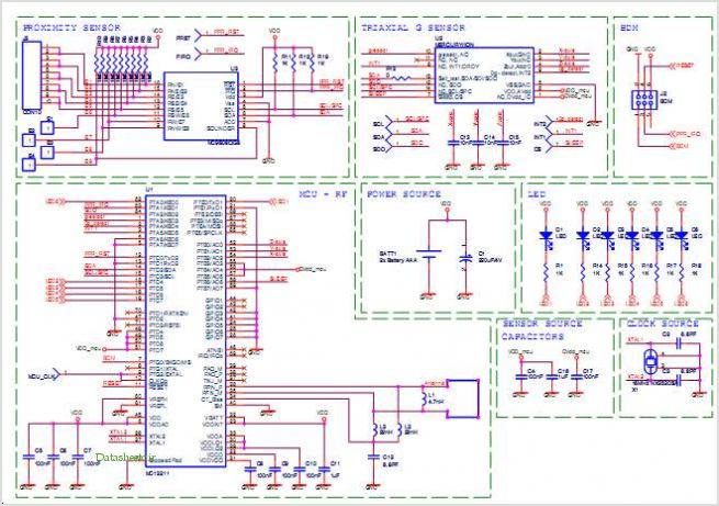
The AD7714 is a precision analog-to-digital converter (ADC) that communicates via a 3-wire serial interface, making it ideal for applications requiring isolation. This interface allows for the integration of optical couplers, which can enhance system safety by isolating high-voltage sections from sensitive microcontroller components. The 80C51 microcontroller, a widely used device in embedded systems, interfaces with the AD7714 using two of its GPIO pins, specifically P3.0 and P3.1, for data communication.
In this configuration, the microcontroller monitors the non-DRDY (Data Ready) bit in the configuration register to ascertain when new data is available in the ADC's Data Register. This method ensures efficient data handling and minimizes the risk of reading data that has not yet been updated. The use of mode 0 in the 80C51's serial communication simplifies the design by utilizing a single data line, which is critical for reducing the number of required connections and potential points of failure in the circuit.
To facilitate data transfer, the DOUT and DIN pins of the AD7714 are directly connected, allowing for bidirectional communication over the same line. When the 80C51 initiates data transfer, the serial clock (SCLK) is set to a high state, signaling the AD7714 to prepare data for transmission. The fixed high state of the POL-side contact ensures stable operation of the ADC during the communication process. This configuration is particularly advantageous in applications where space and component count must be minimized while maintaining reliable performance.3-wire interface to the AD7714 can be equipped with a variety of microcontrollers (including microcontroller or microprocessor). 3-wire serial interface is particularly suitabl e for the isolation system, allows the system used in the optical coupler in an amount of at least. AD7714 and 80C51 (or 87C51,89C51 etc.) microcontroller interface circuit shown in FIG. Minimum opening line 80C51 used only two (P3.0, P3.1). At this time, by the monitoring configuration register non DRDY bit to determine when the Data Register is updated. 80C51 in mode 0 mode due to its serial interface contains a single data line, so the DOUT and DIN end of the AD7714 should be short-circuited.
When transferring data 80C51 serial clock terminal is set to the high level. POL-side fixed contact AD7714 high.
Related Circuits
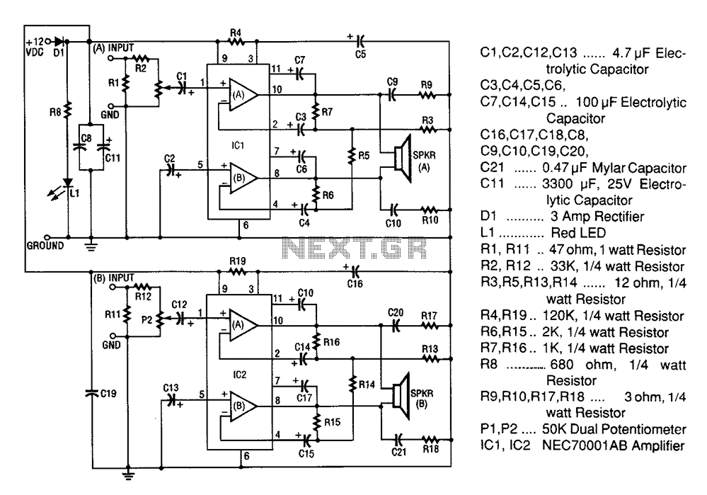
A 20W + 20W stereo amplifier comprises two independent 20-watt RMS amplifiers configured in a bridge arrangement. The input source is connected to a shunt voltage amplifier through resistors R1, R2, and potentiometer P1. Resistor R1 provides load resistance...
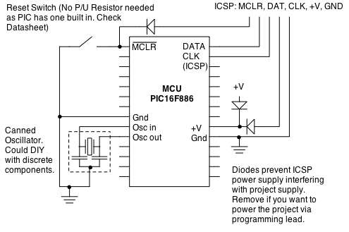
Microcontrollers (MCUs) are versatile integrated circuits (ICs) that enhance the functionality of electronics, robotics, and various other projects. Microcontrollers serve as the brain of embedded systems, providing control, processing, and communication capabilities in a compact form factor. They typically consist...
A basic digital voltmeter circuit utilizing the Harris Semiconductor ICL7107 is presented. It operates within a 2-V range. Calibration involves applying a known voltage of 1.2 V to the input and adjusting resistor R3 to achieve an accurate reading...
This circuit diagram illustrates the design of a straightforward AC voltage converter that transforms 240V AC power into 110V AC. The circuit can effectively be utilized to power electrical devices that necessitate a supply voltage of 110V. The AC voltage...
Many of today's high-performance FPGAs, microprocessors, DSPs, and industrial/embedded subsystems require sequencing of the input power PS10 and PS11. Historically, this has been achieved through: i) discrete methods using comparators, references, and RC circuits; ii) expensive programmable controllers; or...
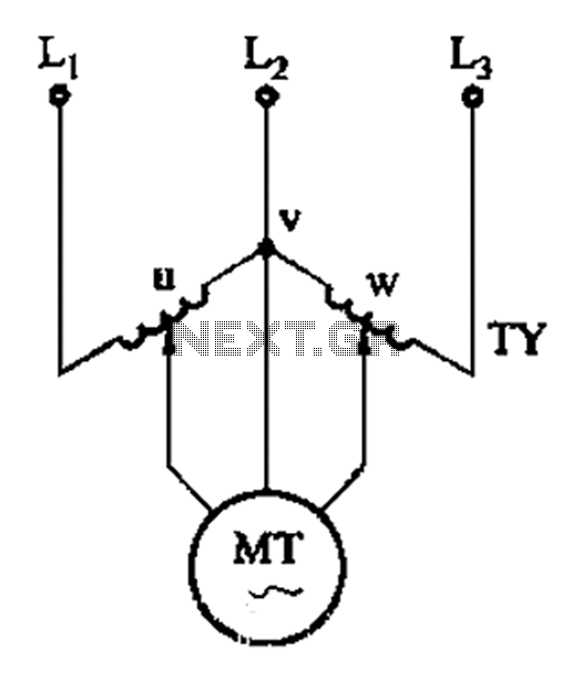
The circuit shown in Figure 3-177 utilizes two single-phase voltage regulators connected to a V-shaped configuration of single-phase regulators. This setup allows for the simultaneous adjustment of voltage and balance, enabling performance akin to a three-phase balanced adjustment. The circuit...