
5 watt, 80 meter QRP CW Transceiver
The described circuit integrates several advanced features aimed at providing a robust and efficient radio communication system. The power output stage utilizes a power MOSFET, which is known for its ability to handle high Voltage Standing Wave Ratio (SWR) conditions without succumbing to thermal runaway, a common issue in traditional bipolar transistor designs. This results in an output of 5 watts, ensuring sufficient power for effective transmission while maintaining a cooler operating temperature.
The receiver section employs a superhetrodyne architecture, which is characterized by its high sensitivity and selectivity. This design allows the receiver to effectively filter and amplify desired signals while minimizing noise. The tuning range of approximately 100 kHz is achieved through the use of a varactor diode, which enables smooth frequency adjustments. Additionally, a switchable Receiver Incremental Tuning (RIT) control enhances operational flexibility, allowing users to fine-tune their reception as needed.
The circuit also features a full break-in keying capability, facilitated by an innovative Transmit/Receive (T/R) switching system. This feature is crucial for operators who require immediate switching between transmitting and receiving modes without delay, thus improving communication efficiency.
Development is ongoing for a printed circuit board (PCB) layout, which will streamline assembly and enhance the reliability of the circuit. The final product is anticipated to be offered as a complete kit, inclusive of all necessary electronic components, the PCB, and a comprehensive instruction manual, making it accessible for hobbyists and engineers alike.
The Variable Frequency Oscillator (VFO) is a critical component of this design, employing a Junction Field Effect Transistor (JFET) to achieve stability. The inclusion of a varactor diode for tuning further enhances the VFO's performance. Compatible alternatives for the JFETs, such as the 2N3819 or 2N4416, can be utilized for Q1 and Q2, provided that the pin configurations are correctly matched to ensure proper functionality. This attention to detail in component selection and circuit design underscores the overall quality and reliability of the system.1. Full 5 watt output using a power MOSFET final that is resistant to high SWR and thermal runaway. This final is very efficient and runs much cooler than traditional bipolar designs. 2. Highly sensitive and selective superhetrodyne receiver with plenty of audio to drive a speaker. About 100 Khz of tuning range is provided through a varactor diode along with a switchable RIT control. 3. Full break-in keying with a unique T/R switching system. Work is continuing on a printed circuit board and this circuit is expected to be available as a complete kit including all electronic parts, PCB and instruction manual at a future date.
My prototype was built on Radio Shack universal boards. This month, we`ll begin by building the VFO. The VFO uses a JFET for stability and a varactor diode to provide the necessary tuning. Many other JFET`s such as the 2N3819 or 2N4416 can be substituted for Q1 and Q2 but pay attention to the pinouts 🔗 External reference
Related Circuits
An inductance meter can be a valuable test instrument for hobbyists. However, few people own them due to their high price. The Inductance Meter Adapter described in this article is a circuit that, when connected to a digital multimeter...
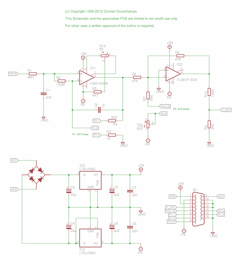
This tiny pH-meter is very tiny: 11cm2 including the PSU circuit! I built it for the College Saint Pierre a few years ago. It is based on a circuit developed at the Facultes Notre-Dame de la Paix, Namur, Belgium....
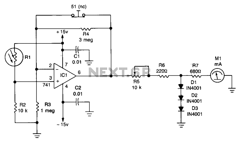
One leg of the photocell (R1) is connected to the +15 volt supply, while the other end is linked to ground through resistor R2, creating a voltage-divider network. The non-inverting input of the 741 operational amplifier (IC1) is connected...
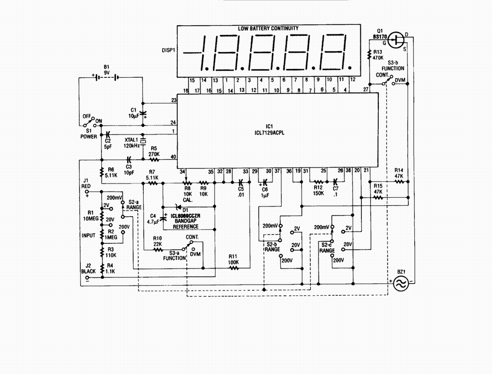
Single-chip digital voltmeter. This 4 1/2-digit DVM circuit is built around a Maxim ICL7129ACPL A/D converter and LCD driver. An ICL8069 CCZR 1.2-V band-gap reference diode is used for accuracy. The described circuit is a single-chip digital voltmeter (DVM) utilizing...
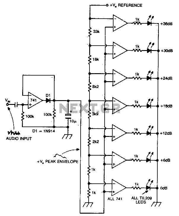
A vertical column of LEDs is configured so that as the audio signal level rises, an increasing number of LEDs illuminate. The LEDs are arranged in increments of 6 dB. The circuit features a fast response time and a...
The series of decibel meters functions to determine the signal strength level delivered to the speakers in an audio system. This decibel meter circuit is commonly referred to as VU meters in high-fidelity audio systems. The series of decibel...
Warning: include(partials/cookie-banner.php): Failed to open stream: Permission denied in /var/www/html/nextgr/view-circuit.php on line 713
Warning: include(): Failed opening 'partials/cookie-banner.php' for inclusion (include_path='.:/usr/share/php') in /var/www/html/nextgr/view-circuit.php on line 713