
50 impedance RF2320 linear amplification circuit diagram
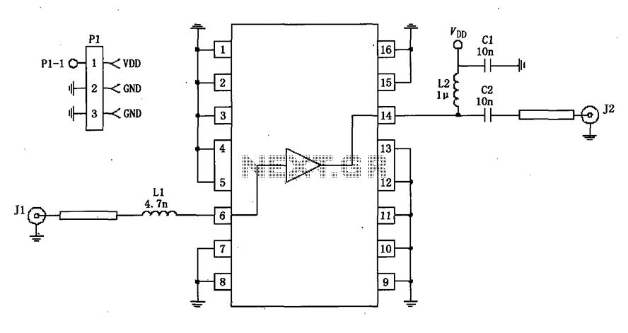
The RF2320 linear amplifier circuit is designed to operate with a 50-ohm impedance, which is a standard value in RF applications, ensuring optimal power transfer and minimal signal reflection. The input and output stages of the amplifier utilize transmission lines, which are critical for maintaining signal integrity and minimizing losses. These transmission lines can be implemented using microstrip or stripline technologies, depending on the PCB design and the desired frequency characteristics.
The matching network is an essential component in this circuit, as it ensures that the amplifier is properly matched to the source and load impedances. This matching can be achieved through the use of inductive or capacitive components, which can be configured in various ways, such as L-networks, T-networks, or π-networks, depending on the specific requirements of the application. The choice of components and their values will depend on the frequency of operation and the specific characteristics of the RF2320 amplifier.
Properly designing the matching network involves calculating the necessary component values to achieve the desired impedance transformation. This can be accomplished using techniques such as Smith chart analysis or computer-aided design (CAD) tools to simulate the circuit performance. The goal is to achieve a flat frequency response over the desired bandwidth while maintaining low insertion loss and high return loss.
In summary, the RF2320 linear amplifier circuit, with its 50-ohm impedance configuration, effectively utilizes transmission lines and matching networks to optimize performance for RF applications. The careful selection and arrangement of inductive and capacitive components are crucial for achieving the desired operational characteristics.50 impedance as shown in Figure grounds RF2320 linear amplifier circuit configured, input, output, using the transmission line and inductive or capacitive constitute matching n etwork.
Related Circuits
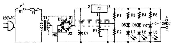
This 0- to 12-Vdc variable power supply utilizes an integrated circuit (IC) voltage regulator along with a robust transformer to deliver a dependable DC power output. The schematic illustrates that transformer T1 has a primary voltage of 120 V...
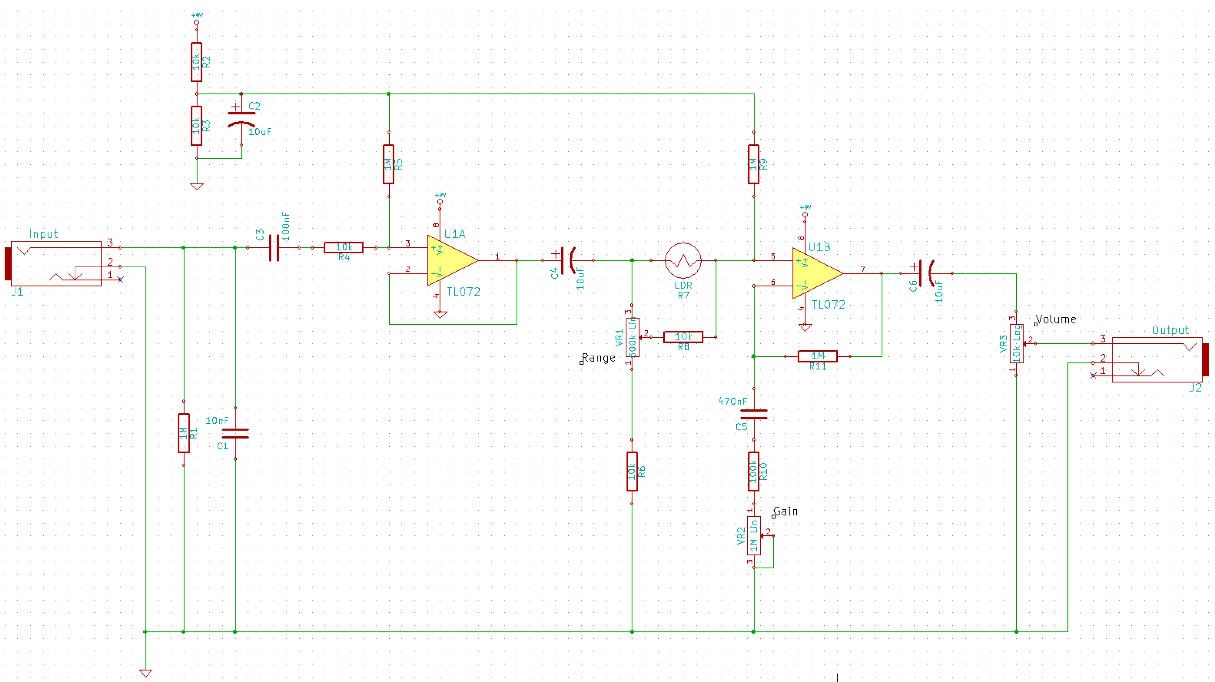
This is a simplified schematic for the Solar Lifeforce. The design eliminates the expression/CV output features and the toggle for the buffer, making it a straightforward circuit. It may benefit from adding small capacitors between R5 and ground, as...
Electric single-girder cranes, also known as electric hoists, are commonly utilized in small factories for lifting and handling equipment. Typically, they are used in conjunction with drag line switching operation, which may not be very convenient. The circuit includes...
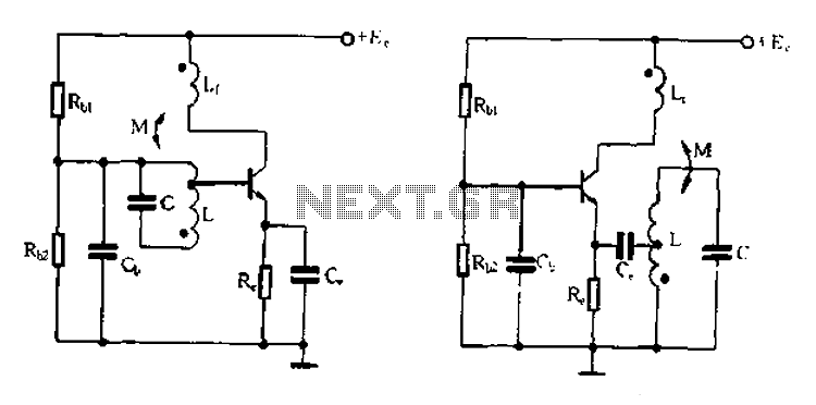
Base frequency selection, frequency-selective emitter type transformer coupled oscillator circuit The described circuit is a transformer-coupled oscillator that utilizes an emitter type configuration to achieve frequency selection. This type of oscillator is designed to generate signals at specific base frequencies,...
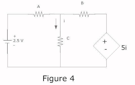
In a complete circuit, there are two types of elements: active and passive elements. Active elements generate energy, while passive elements dissipate energy. Examples of passive elements include resistors and capacitors. In electronic circuits, active and passive components serve distinct...
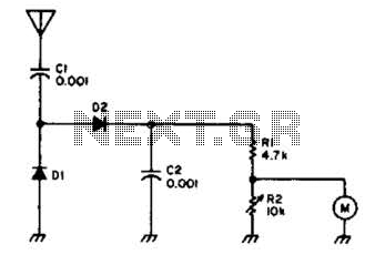
Useful for checking transmitters and antennas, this circuit utilizes a voltage-doubling detector consisting of diodes D1 and D2, which can be HP 5082-2800 hot carrier types or alternatives such as 1N34 or IN82. The circuit incorporates a 100-mA meter...