
50Mhz-trigger
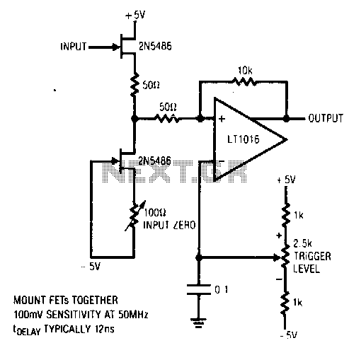
This circuit features a stable trigger with a sensitivity of 100 mV at 50 MHz. It utilizes FETs to create a high-speed buffer, while the LT1016 compares the output of this buffer to the voltage at the trigger level potentiometer, which can be configured for either polarity. A 10 kΩ resistor introduces hysteresis, effectively eliminating chattering caused by noisy input signals. To calibrate the circuit, the input should be grounded, and the input zero control should be adjusted to achieve 0 V at the drain terminal of Q2.
This circuit is designed for high-frequency applications requiring precise triggering capabilities. The 100 mV sensitivity at 50 MHz indicates that it can accurately respond to small voltage changes, making it suitable for environments where signal integrity is critical. The use of FETs provides a high-speed buffer that minimizes signal degradation, ensuring that the output remains faithful to the input signal.
The LT1016 operational amplifier serves as a comparator in this setup, allowing for the comparison of the buffered signal against a user-defined threshold set by the trigger level potentiometer. The inclusion of a potentiometer that can be configured for either polarity adds flexibility to the circuit, enabling it to adapt to various signal conditions and requirements.
The 10 kΩ resistor plays a crucial role in enhancing the circuit's performance by introducing hysteresis. This feature is particularly important in noisy environments, where rapid fluctuations in the input signal can lead to false triggering or chattering. By providing a defined threshold for switching, the hysteresis ensures that the circuit operates reliably, even in the presence of noise.
Calibration is a straightforward process. By grounding the input, the circuit can be adjusted to ensure that the output reflects a true zero voltage level at the drain terminal of Q2. This step is essential for maintaining accuracy and reliability in the circuit's operation, ensuring that it functions as intended across a range of conditions. Overall, this circuit design is effective for applications that require reliable triggering in high-frequency environments.This has a stable trigger 100 m V sensitivity at 50 MHz. The FETs comprise a simple high-speed buffer and the LT1016 compares the buffer"s output to the potential at tbe trigger level potentiometer, which can be of either polarity. The 10-KO resistor provides hysteresis, eliminating "chattering"" caused by noisy input signals. To calibrate this circuit, ground the input and adjust the input zero control for 0 V at Q2"s drain terminal. 🔗 External reference