50Mhz-vhf-crystal-oscillator

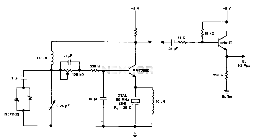
The diagram illustrates a 50 MHz oscillator functioning at its third harmonic. The collector load resistor R1 has been increased due to the rise in the quartz crystal's internal series resistance Rs, which escalates with frequency in the VHF range. The internal series resistance Rs of the crystal is 30 ohms, while the minimum current gain HFI of the transistor is 100. Additionally, employing the same methodology as the 20 MHz oscillator, the external series RLCL equivalent load presented to the 50 MHz crystal is 5.6 ohms (RL) and 1000 pF (CL).
The described 50 MHz oscillator circuit is designed to operate efficiently at its third harmonic frequency. The increase in the collector load resistor R1 is a critical adjustment to accommodate the internal series resistance Rs of the quartz crystal, which is specified at 30 ohms. This resistance is significant in the VHF range, as it can affect the overall performance and stability of the oscillator.
The transistor employed in this circuit has a minimum current gain (HFI) of 100, which is essential for ensuring sufficient amplification of the signal generated by the oscillator. The transistor's gain plays a pivotal role in maintaining the oscillation and ensuring that the output signal is strong enough for further processing or application.
Furthermore, the external series RLCL equivalent load, which is presented to the crystal, consists of a resistive component (RL) of 5.6 ohms and a capacitive component (CL) of 1000 pF. This configuration is crucial for the proper functioning of the oscillator, as it defines the load conditions under which the crystal operates. The values of RL and CL must be carefully selected to ensure that the oscillator maintains its desired frequency and stability.
In summary, this oscillator design integrates the characteristics of the quartz crystal with the transistor's parameters to create a reliable 50 MHz oscillator. The adjustments made to the load resistor and the careful selection of external load components are vital for optimizing performance and ensuring the oscillator operates effectively at its specified frequency.Diagram shows a 50MHz oscillator operating on a third harmonic. The collector"s load resistor R1 has been increased because the quartz crystal"s internal series resistance Rs increases with frequency in the VHF range. The crystal"s internal series resistance Rs is 30ohm, and the transistor"s minimum current gain HFI, is 100.
Using the same technique as for the 20 MHz oscillator, the external series RLCL equivalent load seen by the 50MHz crystal is 5.6ohm (RL) and 1000pF (CL).