
555-Beep-transformer
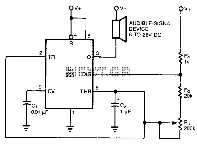
The simple circuit converts the continuous beep of an audible-signal device, such as a Mallory sonalert, into a unique warble or chirp. The values of resistor R and capacitor C2 determine the specific tone quality produced. With a 1kΩ resistor and a 1µF capacitor, the circuit generates a warble similar to the ringtone of an inexpensive phone. Conversely, using a 10µF capacitor produces a chirp akin to the 20kHz back-up alarm of a truck.
An enhancement to this circuit involves utilizing the second section of a 555 timer to drive a piezoelectric transducer instead of a sonalert. This modification would allow for variations in both the pitch of the tone and the rate of the chirp.
The described circuit operates by modulating the output frequency of a sound-generating device to create a more attention-grabbing alert. The core components include a resistor (R) and a capacitor (C2), which form an RC timing circuit. The time constant, determined by the product of R and C2, influences the frequency of oscillation and thus the perceived sound.
In the first configuration, with R set to 1kΩ and C2 at 1µF, the circuit resonates at a frequency that produces a warble effect, which can be particularly useful for applications requiring a distinctive alert sound that stands out from other noise. The sound generated mimics the ringtone of basic mobile phones, making it suitable for consumer electronics.
In the alternative configuration, employing a 10µF capacitor alters the timing characteristics, resulting in a chirp sound that resembles the beeping of a truck's back-up alarm. This sound is designed to be loud and attention-grabbing, enhancing safety in environments where vehicles operate.
The proposed modification using a 555 timer to drive a piezoelectric transducer opens up additional possibilities. The 555 timer can be configured in astable mode to produce a continuous square wave, which can be adjusted in frequency by changing the resistor and capacitor values. This configuration not only allows for pitch variation but also enables control over the duration and frequency of the chirps, providing a more versatile sound output. The piezoelectric transducer is effective in converting electrical signals into sound, making it an ideal choice for applications requiring compact and efficient sound production.
Overall, the circuit's flexibility and adaptability make it suitable for a variety of applications, from consumer electronics to safety alarms, by utilizing simple components to generate distinctive audio signals.The simple circuit transforms the steady beep of an audible-signal device, such as a Mallory sonalert, into a distinctive warble or chirp. The value of R, C2 determines just what tone color you"ll get. With 1k the 1-I"F value shown, the circuit produces a warble similar to the ring tone of an inexpensive phone.
A R, 10-I"F value produces a chirp similar to a truck"s 2ok back-up alarm. One elaboration of this circuit would be to use the second section of a 555 timer to drive a piezoelectric transducer instead of a sonalert; that modification would vary the tone"s pitch, as well as the chirp rate. 🔗 External reference