
555 Duty Cycle Control
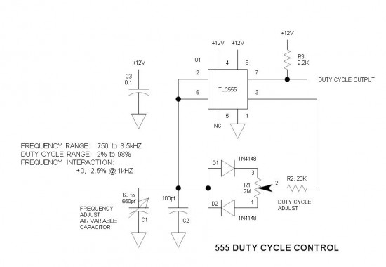
This oscillator circuit utilizes the 555 timer IC in an astable configuration, which is renowned for its versatility in generating square wave signals. The key feature of this design is its ability to vary the duty cycle independently of the frequency, which is achieved through the innovative use of an air-variable capacitor. This capacitor allows for fine-tuning of the frequency while maintaining a constant total resistance in the timing network.
The circuit comprises two main resistors: R1, which is a potentiometer allowing for adjustable duty cycle, and R2, which plays a role in frequency determination. The independent steering diodes (D1 and D2) ensure that the charging and discharging paths of the timing capacitor (C1 and C2) are controlled effectively, allowing for precise timing adjustments.
The output waveform is taken from pin 7 of the 555 timer, which provides a rectangular signal. The pull-up resistor R3 is critical for ensuring that the output can swing to the supply rails, enhancing the circuit's overall performance.
For those seeking to maintain a consistent frequency while adjusting the duty cycle, careful selection of the components is essential. The TLC555 CMOS variant of the 555 timer is particularly advantageous due to its enhanced output characteristics and ability to operate at higher impedances.
The design considerations for this oscillator include the need to balance the values of R1 and C1 to achieve the desired frequency range, as well as the impact of component tolerances on the accuracy of the waveform. The use of an air-variable capacitor, while somewhat antiquated, provides a unique solution for those interested in experimental electronics and can yield rewarding results in terms of performance and versatility.
Overall, this oscillator circuit represents a practical and innovative approach to generating variable duty cycle waveforms while preserving frequency stability, making it a valuable addition to any electronics experimenter's toolkit.A simple oscillator circuit that varies the duty cycle over a wide range without affecting the frequency. It is a variation of the simple 555 astable oscillator. Initially, I told a reader that there was no standard 555 circuit that could do this, but then the grey matter started working.
The use of an air-variable capacitor for frequency control is a mind-blower ”nothing short of a time warp! When potentiometer R1 is centered, operation is obvious and the duty cycle is 50%. However, as R1 is rotated in either direction the charge time and discharge times vary accordingly. The two sides of R1 have independent steering diodes (D1 & D2). C1 & C2 make up the timing capacitor. Pins 2 & 6 of the 555 are the upper and lower thresholds of the input comparators. The charge /discharge voltage is taken from pin 3 because it has rail-to-rail voltage swing, and the open collector output (pin 7) cannot do this. The rectangular waveform output is taken from pin 7 instead. R3 is the pull-up resistor. If constant frequency is desired, C1 could be padded for the correct frequency. However, most experimenters also want variable frequency. Since R1 cannot be varied in total resistance, it cannot vary the frequency. R2 could vary the frequency, but would also affect the duty cycle ratio limits as well. The only practical means of obtaining variable frequency is to vary C1. So we have a charge resistance and a discharge resistance, the sum of which is constant and equal to the R1 potentiometer total resistance (1 to 3).
Therefore, the sum of the charge and discharge times is also constant. Since F = 1/T, the frequency is also be constant. The old-fashioned air variable capacitor is old and klunky. While DigiKey offers no such product, these devices remain available on eBay as used or old stock. Every serious experimenter should have one of these. The one I would buy is a 3-gang 440pf. Wired in parallel the total capacitance is 1320pf. Physical size limitations prevent higher capacitances. To obtain a reasonably low frequency, R1 had to be selected to have as high a resistance as possible. 2M is the highest value pot I had on hand. A 5M would also be a good selection. To function under such high impedance conditions, I selected the TLC555 CMOS 555. A further advantage of this device is that it has rail-to-rail output voltage ”something that the bipolar 555 cannot do.
The accuracy tends to degrade when the slew rate at C1 exceeds about 0. 25V/uS. When this happens, the propagation delay of the comparators becomes significant and the frequency drops somewhat. This causes the peaks of the saw-tooth waveform to skid past the thresholds before the output switches polarity.
This forces the maximum frequency to be lower than about 50kHZ for 50% duty cycle, or lower than 2kHZ with 98% duty cycle. To maintain 1 or 2% frequency accuracy the duty cycle range must drop as frequency increases. 🔗 External reference
Related Circuits
This voltage-controlled oscillator circuit is compact and exhibits good linearity. The precision can be better than 0.01% if properly constructed. The circuit provides three different output waveforms: square, triangle, and sawtooth, which are essential for music synthesizers and measurement...
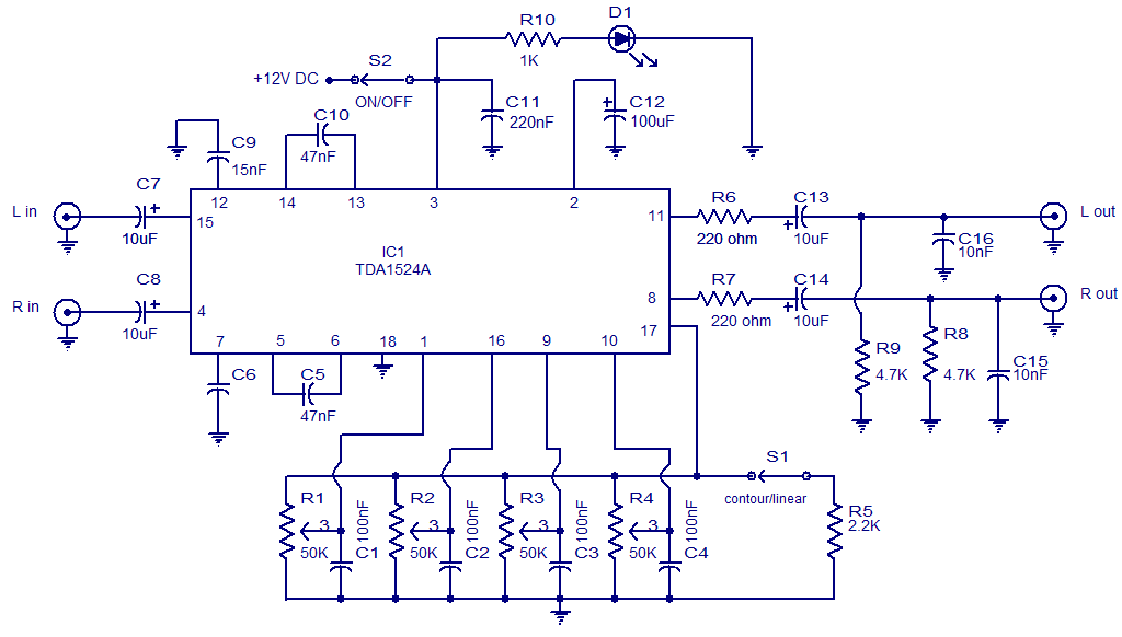
The circuit diagram presents a high-quality stereo preamplifier featuring tone control, utilizing the TDA1524 IC from Philips. This integrated circuit requires minimal external components, operates with low noise, and accommodates a broad power supply voltage range. Potentiometers R1 through...
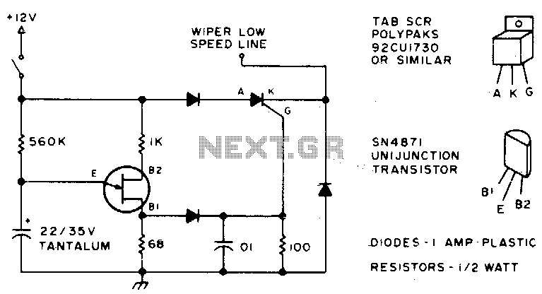
Here is an effective method to configure windshield wipers using an interval circuit. This setup requires only two connections to the car's wiper control, in addition to a ground connection. Variable control can be achieved by replacing a 560...
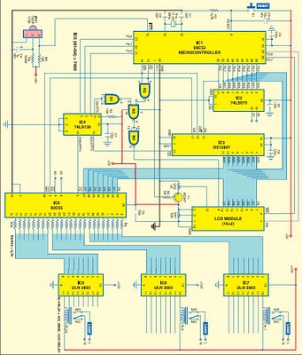
This project is based on the Atmel AT89C52 microcontroller and the Dallas real-time clock (RTC) chip DS12887. It can control and remotely program the switching operations of 24 electrically operated devices, allowing them to be turned on or off...
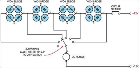
This circuit utilizes the voltage drop across bridge rectifier diodes to create a 5-position variable voltage supply for a DC fan or other small DC motors. While it is not as efficient as a switch-mode circuit, it offers advantages...
A typical circuit for welding equipment is illustrated in the following circuit diagram. The turn-on delay can be accurately controlled with Potentiometer P2, allowing for effective discharge management. The welding equipment circuit typically incorporates several key components to ensure proper...