
555 IC Oscillator with 50% Duty Cycle
The 555 timer IC is a versatile and widely used component in electronic circuits, particularly for generating square wave signals. When configured in astable mode, the 555 timer can produce a continuous square wave output, where the frequency and duty cycle can be adjusted by selecting appropriate resistor and capacitor values.
For symmetric oscillation with a 50% duty cycle, the circuit typically includes two equal resistors (R1 and R2) connected to the discharge and threshold pins of the 555 timer, along with a timing capacitor (C1) connected to the ground. The output frequency (f) can be calculated using the formula:
f = 1.44 / ((R1 + 2R2) * C1)
In this configuration, the charge and discharge times are equal, resulting in a 50% duty cycle.
In addition to the basic 555 oscillator setup, the use of diodes can enhance circuit functionality. Diodes can be incorporated to create distinct charging and discharging paths for the timing capacitor. This allows for greater control over the timing characteristics of the oscillator, enabling variations in duty cycle while maintaining the overall oscillation frequency.
For instance, one diode can be placed in series with the resistor connected to the discharge pin, while another diode can be connected to the resistor linked to the threshold pin. This arrangement allows the capacitor to charge through one path and discharge through another, effectively modifying the duty cycle without altering the frequency significantly.
In summary, a square wave oscillator using the 555 IC can achieve symmetric oscillation with a 50% duty cycle through careful selection of resistor and capacitor values, while the incorporation of diodes provides additional flexibility in managing the charging and discharging processes.A square wave oscillator using 555 IC can be configured to give symmetric oscillation (50% duty cycle). Other circuit uses diodes to split the charging and the. 🔗 External reference
Related Circuits
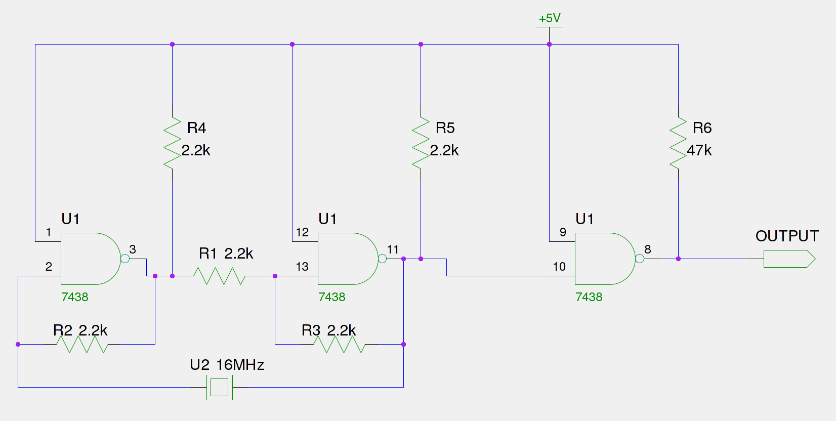
An old Eistar SJ-1 digital pulser has been acquired. However, the frequency it generates is consistently 66% of the expected output. The frequency observed at the frequency stage (Pin 11) is 66% of the 16 MHz crystal, which equates...
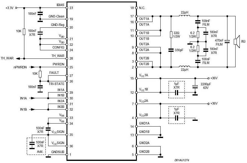
A 1000 Watts audio power amplifier circuit designed for outdoor use. A circuit diagram is needed urgently to facilitate the construction of this high-power amplifier, which is a personal passion project. The design of a 1000 Watts audio power amplifier...
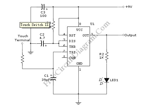
Utilizing the specified values depicted in the schematic diagram, this circuit features a timed ON period of 4 seconds. The ON time is governed by the values of capacitor C2 and resistor R3; increasing either C2 or R3 will...
The circuit is based on the IC1 that is 555, for the creation of alternate flashes from the two led D1-2, that can be also different colour. The frequency of alternation can be regulated from the trimmer R3 and...
Built around a single 8038 waveform generator IC, this circuit produces sine, square or triangle waves from 20Hz to 200kHz in four switched ranges. There are both high and low level outputs which may be adjusted with the level...
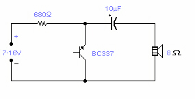
Several NPN transistors can oscillate within the audio frequency range when reverse biased. The minimum supply voltage required is 7V for low-power transistors like the BC109, BC238, and 2N2222A; it increases to 12V for medium-power transistors such as the...
Warning: include(partials/cookie-banner.php): Failed to open stream: Permission denied in /var/www/html/nextgr/view-circuit.php on line 713
Warning: include(): Failed opening 'partials/cookie-banner.php' for inclusion (include_path='.:/usr/share/php') in /var/www/html/nextgr/view-circuit.php on line 713