
555 LED Pulsing Breathing Circuit
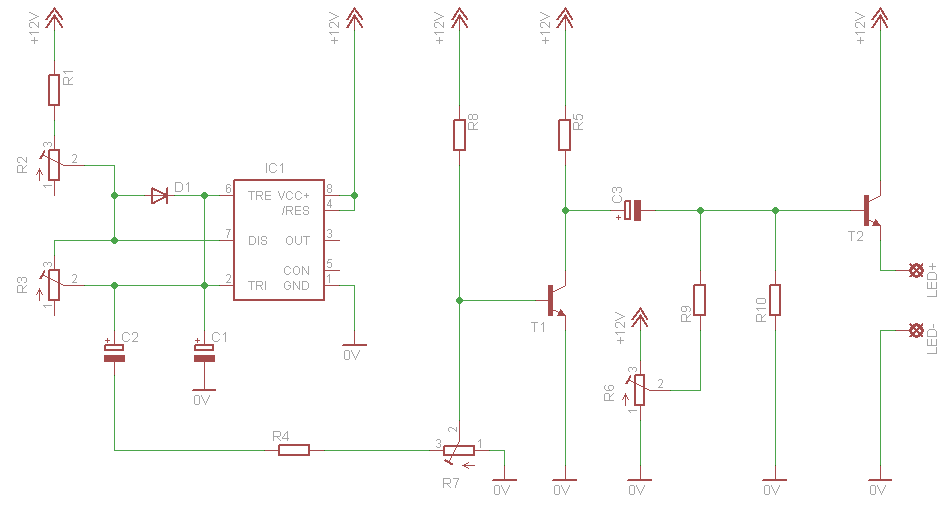
The breathing LED circuit utilizes the 555 timer in astable mode, where it generates a continuous square wave output. This output can be used to control the brightness of the LED by modulating the current through it. The frequency and duty cycle of the square wave can be adjusted by changing the values of resistors and capacitors connected to the timer. Typically, two resistors (R1 and R2) and one capacitor (C1) are used to determine the timing characteristics.
In this circuit, the 555 timer operates with a supply voltage of 5 volts, which is suitable for driving LEDs that require around 3.8 volts. The choice of a lower voltage supply helps to minimize power loss in the transistor used to switch the LED on and off. The transistor, which acts as a switch, is connected to the output pin of the 555 timer, allowing it to handle higher currents required by the LED without overheating or exceeding its ratings.
To ensure the circuit functions correctly at 5 volts, careful selection of resistor and capacitor values is essential. The timing components should be calculated to achieve the desired breathing effect, which typically involves a gradual increase and decrease in brightness. This can create a visually appealing pulsing effect that simulates breathing.
For users attempting to adapt the circuit for a 12-volt supply, it is crucial to recalculate the resistor and capacitor values accordingly, as well as to select a suitable transistor that can handle the increased voltage and current requirements. Additionally, a voltage regulator may be necessary to step down the 12 volts to an appropriate level for the LED operation.
Overall, this breathing LED circuit is an effective and visually engaging project that showcases the versatility of the 555 timer chip in various applications, particularly in decorative lighting for PC modifications.Here is a circuit for simulating breathing / pulsing LED with the 555 timer chip. It became very popular and i received many comments and emails with people that made this circuit and worked fine, as well as comments with people that had troubles converting it to operate at 12 volts supply. It was designed to operate with 5 volts, because i plan to use it for a future PC mod. Since the PC power supply has 5 volts output, and since the LEDs that i plan to use require 3.8 volts to operate, choosing 5 volts for supply was the best choice to minimize power dissipation on the transistor
🔗 External reference
Related Circuits
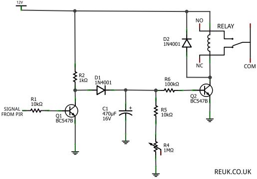
The focus is on 12 Volt DC powered PIR sensors and their associated circuits, which can be directly powered by a 12 Volt battery charged through renewable energy sources such as wind or solar. This article examines how the...
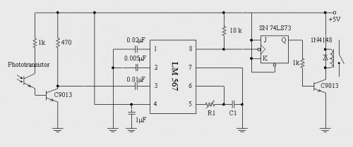
A simple circuit diagram illustrates a schematic for a remote control system, which consists of two parts: the transmitter and the receiver. The transmitter circuit is controlled by an NE555 integrated circuit (IC) and operates by detecting the emitted...
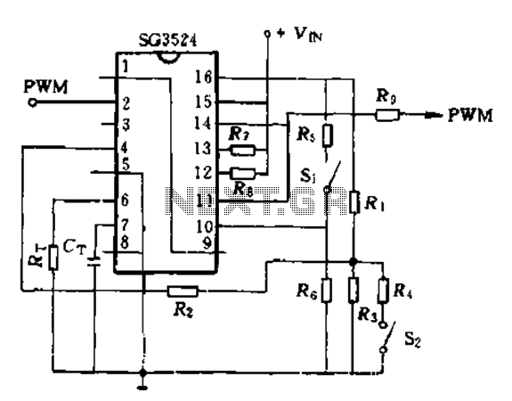
The SG3524 is utilized solely as a pulse width modulator. The error amplifier is configured in a follower arrangement. As illustrated in Figure 10-7, the ACR output connects to PWM output pin 2, which serves as the control signal....
This circuit is designed to signal the exceeding of a fixed threshold in room noise through a flashing LED. Three fixed levels are selectable: 50, 70, and 85 dB. Two operational amplifiers provide the necessary gain for sounds captured...
The regenerative effect of a 4-quadrant inverter necessitates power dissipation in some form. In large industrial drives, this power is typically re-inverted back onto the national grid. However, for smaller applications, implementing a braking circuit is advisable. For low-power...
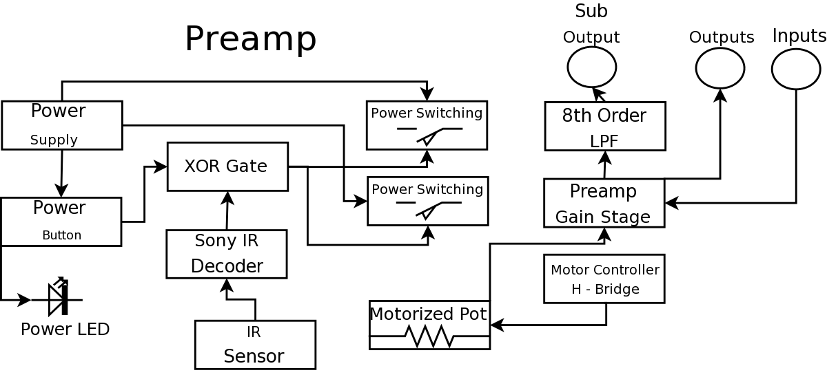
During a Digital Projects Lab, the professor suggested incorporating more circuit-level work into a project. To achieve this, a preamplifier was designed, which included an infrared (IR) remote control to replace a previously built version. The earlier preamplifier functioned...